
Data Sheet for Product

Wiring Guidelines for Gamma Lighting Control Circuits
2
Siemens Industry, Inc.
Gamma Lighting Control Wiring Guidelines
125-3596
2013-01-08
Cable installation can reach its maximum length with three 1000 ft branches from
the power supply. Other topologies are allowed as long as they do not exceed the
maximum length.
Alternative cable segment length is based on comparison of DC resistance and
conductor capacitance with KNX-certified 0.8 mm
2
(20 AWG) cable. Lengths
shown in the following Table meet the KNX time delay specifications.
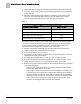
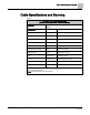
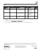
Table 1:
Maximum Length of a TP1 Bus using Alternative Cable.
Description of Cable Segment
6320FE 8771000
Power Supply to End-of-Line Device
1000 ft
End of Line Device to End-of-Line Device
2000 ft
Total Cable Length (due to impedance)
3000 ft
Maximum Parallel Run with Lighting Power
150 ft
Bus voltage is 29 Vdc maximum at the power supply and decreases across the cable
as current is drawn from all devices. Since 18 AWG wire gauge is used, there will be
no loop resistance issues maintaining a minimum of 22 Vdc between the red (+)
terminal and black (–) terminal for the lengths shown in the Table.
Devices communicate at 9600 bps data rate with passive high and active low
signals using the same conductors as the bus power.
End-of-line terminators are not required.
The maximum lengths stated in the Table for the recommended cable ensure total
capacitance for proper communication.
Bus cable 300V insulation allows use with up to 277 Vac lighting circuits.
Bus conductors must be terminated separate from line voltage and must not be in
parallel to the line voltage for runs longer than those shown in the Table.
Both bus conductors must be isolated from ground. This is referred to as
separated
extra-low voltage
(SELV).
– Only the power supply PE terminal is connected to protective earth ground to
prevent static charge build up on the bus.
– Power supply output between the red (+) terminal and black (–) terminal is held
to a maximum of 14 Vdc at the red (+) terminal with respect to the PE terminal.
– The shield is used as a magnetic barrier that is left floating. During installation,
tie back the shields at both ends. If needed later, connect one end of the shield
to the same protective earth ground as the PE terminal on the power supply
and wire nut remaining shields at each TP1 bus terminator.