
Data Sheet for Product
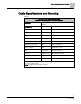

Cable Specifications and Sourcing
3
Siemens Industry, Inc.
Gamma Lighting Control Wiring Guidelines
125-3596
2013-01-08
Analog (1 to 10V) Dimming Control Cable
CAUTION
The electrician must ensure that, when looping lighting power through the dimming
actuator switching relay L-conductors, the maximum connection current of 20A is not
exceeded and that the cable and product are protected by the appropriate lighting
power circuit breaker.
Each analog dimming control channel will sink 1 to 10 Vdc from up to 60 sourcing-type
dimming ballasts. Each dimming channel may be logically grouped with an ON/OFF
dry contact relay for the lighting power.
The recommended dimming control cable is 18 AWG stranded unshielded twisted
pair that is rated 300V plenum. HVAC signal cable is used for this application.
Nominal voltage must not exceed 277V for any cable run in the same conduit or
tray with dimming control cable.
New installations of lighting panels must run both the dimming control cable and
the lighting power cable from the actuator in the lighting panel to the ballast. The
electrician will determine the lighting power cable length, gauge, current-limiting
and separation.
Retrofits to lighting panels only require that new dimming control cable be run and
that an electrician change out the lighting power connections and dimming control
cable connections at the lighting panel and new dimming ballast. Also run KNX bus
wire to each actuator in the lighting panel.
Retrofits without lighting panels may also be done by installing the analog dimming
actuator locally in a utility enclosure at the wire split-off for each circuit to minimize
rewiring the lighting power. KNX bus cable must also be run to each local dimming
actuator.
The ballast manufacturer specifies the required compliance voltage and operating
current. Typical dimming ballasts require a 2 Vdc minimum compliance at 10 Vdc
maximum signal and 2 mA maximum sinking capability. Including overhead and
equipment variance, each dimming channel should be planned to sink 250 mA for
control of up to 60 standard ballasts. Calculate the distance using 4 mA per ballast.
Dimming ballast control requires polarized twisted pair cable, but does not require
shielding.
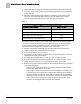
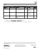
The following Table shows the maximum cable length from each dimming control
channel to the furthest dimming ballast in the group.
Table 2:
Maximum Length of a Single Dimming 1 to 10V Control Cable
Description of Cable Segment
H-TP18-CMP
Cable length to furthest ballast in maximum group of 60 ballasts
640 ft
Cable length to furthest ballast in maximum group of 10 ballasts
1
6,400 ft
Cable length to a single ballast only
1
38,400 ft
1)
Using extended lengths and reduced number of ballasts on a circuit is not reversible without rewiring.