
Data Sheet for Product

instabus EIB
Technical Product Information
January 2004
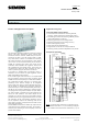
Switch/dim actuator N 526/02 5WG1 526-1AB02
3 x 230 V AC / 6 A
Siemens AG N 526/02, 4 pages Technical Manual
Automation and Drives Group
Electrical Installation Technology Siemens AG 2004 Update: http://www.siemens.com/gamma
P.O. Box 10 09 53, D-93009 Regensburg Subject to change without prior notice
2.5.1.3/1
Product and Applications Description
The switch/dim actuator N 526/02 is a DIN rail mounted
device in N-system dimensions which controls three
dimmable electronic ballasts (DIMM- EVG) for fluores-
cent lamps via their 1-10 V DC control inputs. In addi-
tion, three switch contacts are available for switching
the fluorescent lamps on and off directly. Three bright-
ness sensors can be connected directly to the device N
526/02 for constant light control. The length of the
installation cable between the brightness sensors and
the N 526/02 may not exceed 100 m. The sensors are
connected via a three-core cable, whereby one core is
used as a power supply for the sensor electronics.
If the device is operated with a brightness sensor, a
calibration can be carried out [see brightness sensor
5WG1 255-4AB01 for description).
If the constant light control function is not implemented
and no brightness sensors have been connected, the N
526/02 can also be used purely as a switch/dim actuator.
The switch/dim actuator electronics is supplied inde-
pendently of the EIB bus voltage via an integrated
power supply unit which is linked internally with termi-
nals L3 and N. It is therefore also possible to switch the
fluorescent lamps on and off independently of the EIB, if
the EIB has not yet been installed or a relevant applica-
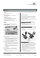
tion program has not yet been loaded. One push button
per switch output is available on the front plate of the
device for local operation. The switch output can be
switched on or off by pressing the push button briefly
[TOGGLE function]. A long push button action can start
the calibration of the corresponding brightness sensor
for the respective output. The switching state of the
three switch contacts is displayed via three LEDs on the
front plate of the device.
Several DIMM- EVG electronic ballasts per output can be
controlled with one switch/dim actuator. The number is
limited by the switching or control capacity of the out-
puts of the N 526/02.
Application Programs
20 A3 Switch/dim actuator 905303
• 3-fold switch/dim actuator for switching ON/OFF,
dimming, setting values and constant light control
• Constant light control and switching ON/OFF possible
without dependence on the bus
• Switching possibility on bus voltage failure
• Switching possibility on bus voltage recovery
• Status interrogation possible
• Initial value can be parameterised
• “Night mode” can be set via local push buttons
• “Cleaning mode” possible via adjustable time periods
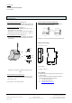
Example of Operation
Load circuit
PE
AC 230 V D C 1...10 V
Su pp ly Control
Sensor A
Switching B
AC 230 V
AC 230 V
Switching A
L1
L2
GND
L3
VCC
IN
Brightness sensor A
L
GND
VCC
Out
AC 230/400 V
L1
GND
Sensor B
DC 1...10 V
Dimming A
Dimming B
DC 1...10 V
Bus coupler
instabus EIB
GND
1-10V
GND
VCC
IN
1-10V
GND
Switch/dim actuator
Sensor C
DC 1...10 V
Dimming C
N 526/02
GND
VCC
IN
1-10V
L3
L2
GND
DIMM- EVG A
Brightness sensor B
Su pp ly Control
DIMM- EVG B
N
+
-
PE
L
N
-
+
GND
Out
VCC
Lamp
AC 230 V D C 1...10 V
Lamp
Brightness sensor C
Su pp ly Control
DIMM- EVG C
PE
L
N
+
-
PE
N
AC 230 V DC 1 ...10 V
VCC
Out
Lamp
N
AC 230 V
B
C
A
Integrated
power supply
Switching C
Note: Co-phasal outer conductors of a network can be
connected to terminals L1, L2, L3 according to diagram
1, A1 instead of the various outer conductors L1, L2, L3.