
Data Sheet for Product

instabus EIB
Technical Product Information
January 2004
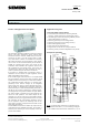
Switch/dim actuator N 526/02 5WG1 526-1AB02
3 x 230 V AC / 6 A
Technical Manual N 526/02, 4 pages Siemens AG
Automation and Drives Group
Update: http://www.siemens.com/gamma Siemens AG 2004 Electrical Installation Technology
Subject to change without prior notice P.O. Box 10 09 53, D-93009 Regensburg
2.5.1.3/2
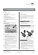
Installation Instructions
• The device may be used for permanent interior instal-
lations in dry locations within distribution boards or
small casings with DIN rail EN 60715-TH35-7,5.
V
WARNING
• The device must be mounted and commissioned by
an authorised electrician.
• When connecting the device, it is important to ensure
that the device can be isolated, particularly when
connecting several current paths.
• The prevailing safety and accident regulations must
be observed.
• The device must not be opened.
• For planning and construction of electric installations,
the relevant guidelines, regulations and standards of
the respective country are to be considered.
Technical Specifications
Power supply
• Bus voltage: via the bus line
• N 526/02 electronics: integrated power supply unit
(230 V AV +10% / -15%) which is supplied via termi-
nals L3 and N.
Inputs
• Number: 3 (for brightness sensor 5WG1 255-4AB01 or
5WG1 255-4AB02)
- Connection of a brightness sensor via a three-core
cable with a maximum length of 100 m; the power
supply of the sensor electronics is also carried out
via this cable
Outputs
• 3 switch outputs
- rated voltage: AC 230 V, 50 ... 60 Hz
- rated current: 6 A (resistive load)
• 3 control voltage outputs (1-10 V DC)
Switching capacity of an output at AC 230 V
• Osram Quicktronic® dimmable single lamp for 1x58 W
FL: max. 20
• Osram Quicktronic® dimmable single lamp for 1x36 W
FL: max. 30
• Osram Quicktronic® dimmable twin lamp for 2x58 W
FL: max. 10
• Osram Quicktronic® dimmable twin lamp for 2x36 W
FL: max. 15
Control voltage
• DC 1 ... 10 V (from DIMM- EVG)
Control power
• max. 50 Siemens DIMM- EVG
Operating elements
• 1 programming button for toggling between normal
mode/addressing mode
• 3 buttons for local operation of the switch/dim actua-
tor, independently of EIB
Display elements
• 1 red LED: for checking the bus voltage and for dis-
playing normal mode/addressing mode
• 3 red LEDs: for displaying the switching state of the
switch outputs
• 1 green LED for displaying the operating voltage
Connections
• Screw terminals
- Insulation strip length 9 ... 10 mm
2 x 0.5...2.5 mm² single-core or 2 x 0.5...1.5 mm²
finely-stranded with connector sleeve
• Bus line: screwless bus terminal
0.6 ... 0.8 mm ∅ single-core
• Cable for connecting the brightness sensor:
JY(St)Y 2x2x0.8 (should be laid separately from the
230 V cables). VDE 0100 T520 should be observed.
• Electronic ballast control circuit: control cable in ac-
cordance with the data from the manufacturer of the
electronic ballast. VDE 0100 T520 should be ob-
served.
Mechanical data
• Housing: plastic
• Colour of housing: light grey
• Dimensions: DIN rail mounted device in N-system
dimensions, width = 6 modules (1 module = 18 mm)
• Weight: approx. 405g
• Fire load: approx. 5300kJ +
10%
• Installation: clip-on mounting onto DIN rail
DIN EN 50022-35 x 7.5
Electrical safety
•
Degree of pollution (in accordance with IEC 60664-1): 2
• Type of protection (in accordance with EN 60529):
IP 20
• Overvoltage category (according to IEC 60664-1):III
• Bus: safety extra-low voltage SELV DC 24 V
• Device complies with:
EN 50090-2-2 and EN 60669-2-1