
Data Sheet for Product

instabus EIB
Technical Product Information
January 2004
Switch/dim actuator N 526/02 5WG1 526-1AB02
3 x 230 V AC / 6 A
Siemens AG N 526/02, 4 pages Technical Manual
Automation and Drives Group
Electrical Installation Technology Siemens AG 2004 Update: http://www.siemens.com/gamma
P.O. Box 10 09 53, D-93009 Regensburg Subject to change without prior notice
2.5.1.3/3
Reliability
• Failure rate: 939 fit at 40 °C
EMC requirements
• Complies with: EN 50081-1 and EN 50082-2,
EN 50090-2-2
Environmental conditions
• Climatic withstand capability: EN 50090-2-2
• Ambient operating temperature: -5 ... +45 °C
• Storage temperature: -25 ... + 70 °C
• Relative humidity (not condensing): 5% ... 93%
Markings
KNX / EIB
Location and Function of the Display and
Operator Elements
A
4
A5
A6
A7
A8
A9
A11
A
B
C
A
B
C
Sensor A
IN VCC GND
EVG 1
ballast A
1 - 10V
GND
Sensor C
IN
VCC
GND
EVG 3
ballast C
1 - 10V
GND
Sensor B
IN VCC GND
EVG 2
ballast B
1 - 10V
GND
L1
L2
L3
N
IN
SIEMEN S
5WG1 52 6-1 AB02
instab us
EIB
Schalt-/Dimmaktor
Switching/Dimming Actuator
Un ~230V In 6A
Betr ieb
operat ion
Phys.
Adr.:
Ber./Area:
Lin./Line:
TIn. / Dev.:
V2.10
+ -
21R0
u u u
A10
A
3
A
12
A
2
A
1
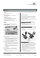
Diagram 1: Location of the display and operator elements
A1 Screw terminals for connecting the mains voltage
A2 Operational LED
A3 Push button for local operation of the three switch
outputs or longer operation (>6 sec.) for calibra-
tion of the respective brightness sensors
A4 Screw terminals for connecting the switch outputs
in order to switch the DIMM- EVGs on and off
A5 Plug for bus connecting terminal
A6 LED for displaying normal mode (LED off) or ad-
dressing mode (LED on); it is extinguished auto-
matically once the physical address has been trans-
ferred
A7 Learning button for toggling between normal
mode and addressing mode for transferring the
physical address
A8 Type label
A9 Terminal assignment of the screw terminals
A10 Screw terminals for connecting the brightness
sensors
A11 Screw terminals for connecting the control circuits
of the electronic ballasts
A12 LEDs for displaying the switching state of the out-
puts
Mounting and Wiring
The N-system DIN rail mounted device (6 modules) can
be inserted in the N-system distribution board, either
surface- or flush-mounted and wherever EN 50022-35 x
7.5 DIN rails are available.
The connection with the bus line is carried out via a bus
terminal.
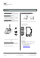
Installing the DIN rail mounted device
(Diagram 2)
- Slide the DIN rail mounted device (B1) onto the DIN
rail (B2) and
- rotate the device downwards until the slide switch
audibly clicks into position.
Dismantling the DIN rail mounted device
(Diagram 2)
- Remove all connected cables,
- press the slide switch (C3) downwards with a screw-
driver and
- remove the device (C1) from the DIN rail (C2) with a
swivel action.
B1
C1
C2
C3
B2
Diagram 2: Installing and dismantling the DIN rail moun-
ted device
Removing the bus terminal [Diagram 3)
- The bus terminal is located on top of the device.
- The bus terminal (D2) consists of two sections (D2.1,
D2.2), each with four terminal contacts. Care should
be taken not to damage the two test sockets (D2.3),
either by accidentally connecting them to the bus
conductor or with the screwdriver (when trying to
remove the bus terminal].
- Carefully insert the screwdriver in the wire entry slot
underneath the bus terminal (D2) and pull the bus
terminal forwards out of the switch/dim actuator
N 526/02 (D1].
Note: Care should be taken as there is a risk of shorting
when removing the device.