
Data Sheet for Product

instabus EIB
Technical Product Information
January 2004
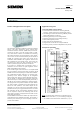
Switch/dim actuator N 526/02 5WG1 526-1AB02
3 x 230 V AC / 6 A
Technical Manual N 526/02, 4 pages Siemens AG
Automation and Drives Group
Update: http://www.siemens.com/gamma Siemens AG 2004 Electrical Installation Technology
Subject to change without prior notice P.O. Box 10 09 53, D-93009 Regensburg
2.5.1.3/4
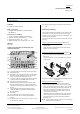
Connecting the bus terminal
(Diagram 3)
- Place the bus terminal in the guide slot and press the
bus terminal (D2) backwards until it reaches the stop.
Connecting the bus cable
(Diagram 3)
- The bus terminal (D2) is suitable for single core con-
ductors with 0.6... 0.8 mm Ø.
-
Strip approx. 5 mm of insulation from the conductor
(D2.4) and plug in the terminal (D2) (red = +, black = -).
Disconnecting the bus cable (Diagram 3)
- Remove the bus terminal (D2) and pull the conductor
(D2.4) out of the bus cable by rotating it backwards
and forwards.
Diagram 3: Connecting and disconnecting the bus
cable
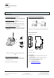
Connecting load circuits (Diagram 4)
- Strip approx. 8 … 9 mm of insulation from the con-
ductor (F1.1], plug in the terminals (F1) and tighten
the screws (F1.2).
Cross sections: “see Technical data”
Disconnecting load circuits (Diagram 4)
- Loosen the screw (G1.2) and pull the conductor
(G1.1) out of the terminal (G1).
Diagram 4: Connecting and disconnecting load circuits
Dimension drawing
Dimensions in mm
b
90
45
55
44
b = 6 module
1 module = 18 mm
General Notes
• Any faulty devices should be returned to the local
Siemens office.
• If you have further questions about the product,
please contact our Technical Support:
℡ +49 (0) 180 50 50-222
" +49 (0) 180 50 50-223
! adsupport@siemens.com
D1
D2
D2
D2.4
D2
D2.
4
5 m
m
D2.1 D2.2
D2
D2.3