
Data Sheet for Product

GAMMA instabus
Technical product information
August 2006
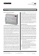
Venetian blind actuator N 522/03 5WG1 522-1AB03
4 x 230 V AC / 8 A
Siemens AG N 522/03, 4 pages Technical manual
Automation and Drives Group
Electrical Installation Technology © Siemens AG 2006 Update: http://www.siemens.com/gamma
P.O. Box 10 09 53, D-93009 Regensburg Subject to change without further notice
2.10.1.16/1
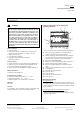
Product and functional description
The Venetian blind actuator N 522/03 is a DIN rail mounted
device with N-system dimensions and a width of 6 module
units. It can control four independent drives for carrying
out blind movement and slats adjustment. Apart from the
possibility to drive the sun-/sight guard directly into one of
its two final positions it is also possible for both the blind
and the slats to be moved independently into intermediate
positions, defined in percentages, by positioning com-
mands. The accuracy achieved by the positioning of the
blind or the slats depends on the motor and drive used and
not on the Venetian blind actuator.
Drives (motors) with electromechanical limit switches as
well as drives with integrated electronic limit switches can
be connected to the outputs of the N 522/03. It is not per-
mitted to connect both types of drives to the same output
or to connect drives with electromechanical limit switches
in parallel, since the opening of the drive’s limit switches is
queried by the actuator and used to synchronize the
movement times into the final positions. If a drive with in-
tegrated limit switch electronics is used the movement
times into the final positions are not adjusted automati-
cally. These drives are controlled exclusively by using the
movement times from one final position to the other.
Therefore the movement times of the motors should be
measured as exactly as possible and set in the application
program. When connecting a relay for group control of
several drives to an output of the N522/03 this relay has to
be controlled like a drive with integrated limit switch elec-
tronics.
The actuator electronics are supplied via an integrated
power supply unit for AC 230V, independent of the KNX
bus voltage. In direct mode it is therefore possible to carry
out shutter movement or slats adjustment independently
of the bus, even if no bus voltage is available, the N 522/03
still has to be taken into operation with the ETS (Engineer-
ing Tool Software) or communication over the bus has
been interrupted.
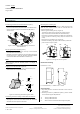
With the N 522/03, "direct mode" is switched on by means
of a pushbutton at bottom left on the upper side of the ac-
tuator. When this pushbutton is pressed for the first time,
the yellow LED shines with a steady light to indicate the di-
rect mode. This mode can be terminated either at any time
with another press of the "direct mode" pushbutton or it
will be terminated automatically if the set On-period ex-
pires without any pushbutton being pressed during this
time. The yellow LED for indicating direct mode then goes
out and the actuator is back in bus mode.
There are two push buttons available per drive output on
the upper side of the Venetian blind actuator for direct op-
eration. This is carried out via long and short push button
actions in the same way as via a KNX push button.
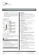
Application program
The Venetian blind actuator N 522/03 can be used to-
gether only with application program 25 A4 Sunblind
981101, which can be configured and loaded with the En-
gineering Tool Software (ETS) from version ETS2 V1.3.
The program is structured so that, in the supplied state,
there is sufficient basic functionality in combination with
12 basic communication objects for a simple application in
standard mode available: the “Status direct mode” object,
an “Alarm” object that influences all channels, a “Move-
ment blockade” object that also influences all channels, a
“Sun blind, central up/down” object that influences all
channels, and two 1-bit command objects per channel
which make it possible to move a blind to one of its limit
positions and to stop the movement or to stepwise adjust
the slats.
It can be selected via the ETS parameter window “Func-
tions, Objects” whether each channel should be configured
individually or whether configuration should be carried out
identically for all channels together. Furthermore, the fol-
lowing functions and objects can be added as needed per
device or per channel:
− An 8-bit scene control integrated into the actuator,
− Two 1-bit objects for saving and restoring any two de-
sired sun protection positions 1 and 2,
− One “Alarm” object per channel,
− One “Movement blockade” object per channel,
− One “Sun blind, central up/down” object per channel.
In addition to the setting of the type of sun protection and
the limit switching for all channels or the respective chan-
nel, further objects can be added via the parameter win-
dow “Channel A-D” resp. “Channel x”:
− The objects for automatic mode,
− Two 8-bit command objects in standard mode (blind
and slat position in %),