
Data Sheet for Product

GAMMA instabus
Technical product information
August 2006
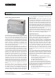
Venetian blind actuator N 522/03 5WG1 522-1AB03
4 x 230 V AC / 8 A
Technical manual N 522/03, 4 pages Siemens AG
Automation and Drives Group
Update: http://www.siemens.com/gamma © Siemens AG 2006 Electrical Installation Technology
Subject to change without further notice P.O. Box 10 09 53, D-93009 Regensburg
2.10.1.16/2
− Two 8-bit status objects (blind and slat position in %)
and optionally
− One “Sunshine on/off” object per device or channel
that is used with the use of a blind control module to
lock/release the blind and slat positioning in automatic
mode after optionally the blind was moved to the up-
per or lower limit position.
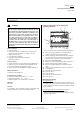
Connection example
Jalousieaktor N522/03
Venetian blind actuator N 522/03
Busankoppler
Bus coupling unit
K1
Auf
Up
K2
Ab
Down
M
1~
Jalousie
Venetian blind
Kanal A
Channel A
N
K3
Auf
Up
K4
Ab
Down
M
1~
N
K5
Auf
Up
K6
Ab
Down
M
1~
N
K7
Auf
Up
K8
Ab
Down
M
1~
N
L2
NL1
instabus EIB
Jalousie
Venetian blind
Kanal B
Channel B
Jalousie
Venetian blind
Kanal C
Channel C
Jalousie
Venetian blind
Kanal D
Channel D
Jalousieantriebe
Venetian blind drives
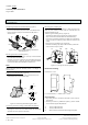
Notes for installation
The device may be used for permanent interior installa-
tions in dry locations within distribution boards or small
casings with DIN rail EN 60715-TH35-7.5.
V
DANGER
• The device must be mounted and commissioned by an
authorised electrician.
• When connecting the device, it should be ensured that
the device can be isolated.
• The device must not be opened.
• For planning and construction of electric installations,
the relevant guidelines, regulations and standards of the
respective country are to be considered.
• In the case of motors with electronic limit switches, the
switching points must be adapted on site.
Technical data
Power supply
• KNX bus voltage: carried out via the bus line
• KNX bus current: 5 mA (only half a standard bus load!)
• Electronics:
- integrated power supply for AC 230 V, +10 % / -15 %,
50 Hz
- Mains connection: 2-pole (terminals L1 and N)
- Power consumption: max. 1.5 W
Operating elements
• 1 push button:
for toggling between normal mode / addressing mode
• 1 push button:
for toggling between bus / direct operation
• 4 x 2 push buttons:
for direct operation of the Venetian blind drives,
independent of the KNX bus
Display elements
• 1 red LED: for displaying
normal mode / addressing mode (off / on)
• 1 green LED: for displaying
the operating voltage (On = AC 230V available)
• 1 yellow LED: for displaying
bus / direct operation (off / on)
Inputs/outputs
• Mains connection: 2-pole (L1, L2) and 2x 5-pole for
- supplying the internal electronics via the terminals for
L1 and N,
- the outputs A and B via the terminal for L1,
- the outputs C and D via the terminal for L2
- and for looping through the N- and PE-conductors to
the connected motors.
• 4 load outputs for 4 drives: 4-pole (DOWN; UP; N, PE)
- Rated voltage: AC 230 V, 50 Hz
- Rated current: 8 A (resistive load) per relay contact
- Switching cycles: >20.000 for cos ϕ = 0.4 and I = 2 A
Connections
• Mains and output circuits:
- Plug-in terminals, insulation strip length 9 ... 10 mm
• The following conductor cross-sections are permitted:
- 0.5 ... 2.5 mm² single-core
- 0.5... 2.5 mm² finely stranded with plug connector,
sealed crimp connection
- 0.5 ... 1.5 mm² finely stranded, with connector sleeve
• EIB-Bus line:
- pressure contacts on data rail,
- screw-less bus connection block,
- 0.6 … 0.8 mm Ø single core, insulation strip length
5 mm