
Data Sheet for Product

GAMMA instabus
Technical product information
August 2006
Venetian blind actuator N 522/03 5WG1 522-1AB03
4 x 230 V AC / 8 A
Siemens AG N 522/03, 4 pages Technical manual
Automation and Drives Group
Electrical Installation Technology © Siemens AG 2006 Update: http://www.siemens.com/gamma
P.O. Box 10 09 53, D-93009 Regensburg Subject to change without further notice
2.10.1.16/3
V
DANGER
Due to the permitted printed conductor load care
has to be taken when looping through the N- and
PE-conductor that the total terminal current of 10 A
may not be exceeded! If different L-conductors are
connected to L1 and L2 each of them must be fused
with a circuit-breaker of characteristic B or C for a
max. rated current of 10 A. If the same L-conductor
is connected to terminal L1 and to L2 then this L-
conductor must be fused with a circuit-breaker of
characteristic B or C for a max. rated current of 10
A. The PE and N terminals may only be used for
connecting the blind motors that are controlled by
the device.
Mechanical data
• Housing: plastic
• Dimensions: DIN rail mounted device in N-system di-
mensions, width: 6 modules (1 module = 18 mm)
• Weight: approx. 335 g
• Fire load: approx. 4650 KJ
• Installation: snap-on fixing onto DIN rail
EN 60715-TH35-7.5
Electrical safety
• Degree of pollution (in accordance with IEC 60664-1): 2
• Protection type (in accordance with EN 60529): IP 20
• Bus: safety extra-low voltage SELV DC 24 V
• Device complies with EN 50090-2-2 and EN 60669-2-1
EMC requirements
complies with EN 50090-2-2
Environmental conditions
• Ambient operating temperature: - 5 ... + 45 °C
• Storage temperature: - 25 ... + 70 °C
• Relative humidity (not condensing): 5 % to 93 %
Markings
KNX / EIB
CE mark
In accordance with the EMC guideline (residential and
functional buildings) and the low voltage guideline
Location and function of the display and
operating elements
A8
A9
A10
A13
A12A11
A1
A2
A3
A4
A5
A6
A7
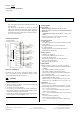
Figure 1: Location of the display and operating elements
A1 Button for toggling between normal / addressing
mode for transferring the physical address
A2 LED for displaying normal mode (LED off) or address-
ing mode (LED on); it is automatically extinguished
once the physical address has been transferred
A3 Plug for bus connection block
A4 Buttons for direct operation of the drive outputs A…D
A5 LED for displaying the operating voltage
A6 Button for toggling between bus mode and direct
mode
A7 LED for displaying when direct mode is switched on
A8 Terminal for L1
A9 Terminals for outputs A and B
A10 Terminals for N
A11 Terminals for PE
A12 Terminals for outputs C and D
A13 Terminal for L2
Mounting and wiring
General description
The DIN rail mounted device with N-system dimensions can
be inserted in N-system distribution boards, either surface-
or flush-mounted, and wherever DIN rails EN 60715-TH35-
7.5 are available.
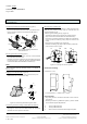
Assembling the DIN rail mounted device (Figure 2)
- Place the device (B1) on the DIN rail (B2) and
- rotate the device downwards until the slide switch audi-
bly clicks into position.