
Data Sheet for Product

GAMMA instabus
Technical product information
August 2006
Venetian blind actuator N 522/03 5WG1 522-1AB03
4 x 230 V AC / 8 A
Technical manual N 522/03, 4 pages Siemens AG
Automation and Drives Group
Update: http://www.siemens.com/gamma © Siemens AG 2006 Electrical Installation Technology
Subject to change without further notice P.O. Box 10 09 53, D-93009 Regensburg
2.10.1.16/4
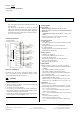
Dismantling the DIN rail mounted device (Figure 2)
- Remove all the connected cables,
- press the slide switch (B3) down with a screwdriver and
- remove the device (B1) from the DIN rail (B2) with a
swivel action.
B1
B1
B
2
B2
B3
Figure 2: Assembling and dismantling the DIN rail
mounted device
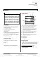
Removing the bus terminal
(Figure 3)
- The bus terminal is located on the top of the Venetian
blind actuator N 522/03 (C1)
- Carefully insert the screwdriver into the black part of the
bus terminal (C2.1) and pull the bus terminal forwards
out of the Venetian blind actuator N 522/03 (C1).
Note
When removing the bus terminal, there is a danger of
short circuits.
Plugging in the bus terminal
(Figure 3)
- Place the bus terminal (C2) in the guide slot and press
downwards until it reaches the stop.
C1
C2
C2
C2.4
C2
C2.4
5 mm
C2.1 C2.2
2
C2.3
C
Figure 3: Connecting and removing the cable
Connecting the mains voltage and Venetian blind drives
- The connections are carried out with plug-in terminals.
- Strip approx. 9-10 mm of insulation from the conductor
and slide into the respective terminal.
Mounting the insulating cap
If the device should be mounted on a DIN rail without an
data rail, the contact system must be covered with the
supplied insulating cap.
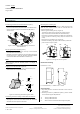
- Removing the locating clamp: (Figure 4)
The locating clamp (D3) encloses the contact system
(D2) on the rear of the Venetian blind actuator (D1).
Insert the screwdriver between the DIN rail mounted de-
vice (D1) and the locating clamp (D3) and remove the
clamp.
- Clipping on the insulation cap: (Figure 4)
Place the insulating cap (D4) on the contact system and
press so that it snaps in place.
Figure 4: Covering the contact system
Dimension drawing
Dimensions in mm
b
90
44
55
45
b = 6 module units; 1 module unit = 18 mm
General notes
• Any faulty devices should be returned to the local Sie-
mens office.
• Should you have any additional queries, please contact
our Technical Support department:
℡ +49 (0) 180 50 50-222
" +49 (0) 180 50 50-223
! www.siemens.com/automation/support-request
D
D1
D2
D2
D4
D1