
Data Sheet for Product

GAMMA instabus
Technical Product Information
February 2007
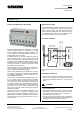
Switching/Dimming Actuator N 526E02 5WG1 526-1EB02
8x AC 230 V / 16 A
Technical manual N 526E02, 4 pages Siemens AG
Automation and Drives Group
Update: http://www.siemens.com/gamma © Siemens AG 2007 Electrical Installation Technology
Subject to change without prior notice P.O.Box 10 09 53, D-93009 Regensburg
2.5.1.12/2
Technical specifications
Power supply
• Bus voltage: carried out via the bus line
• Bus current:: Notice: the device represents at least a
double bus load and takes up to 30 mA from the bus.
Outputs
• number: 8 outputs (latch relays, potential free con-
tacts)
• rated voltage: AC 230 V, 50 ... 60 Hz
• rated current: 16 A, cos phi = 1
• switching current at AC 230 V: 0,1 ... 16 A, cos phi = 1
• DC switching current:
- DC 10 ... 30 V: max. 16 A, resistive load
- DC 230 V: max. 0,18 A, resistive load
• switching characteristic: to be set in parameter list
(see application program description)
Control voltage
• 1 ... 10 V (provided by dimmable ballast)
• in case of bus voltage failure: 10 V
Control power
• dimmable electronic ballast: max 60 units
• signal amplifier: max 12 units
CAUTION
There is no protection of the control circuits against
destruction by accidental connection to AC 230 V !
Operating elements
• 1 learning push button:
for toggling between normal mode/addressing mode
• 8 slide switches for manual operation
(slide in upper position: relay contact open = OFF,
slide in lower position: relay contact closed = ON)
Display elements
• 1 red LED:
for checking the bus voltage and for displaying normal
mode/addressing mode
• 8 slide switches for displaying the switching position
per channel (see above)
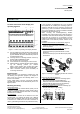
Connections
• load and control circuit, physical:
insulation strip length 8 ... 9 mm
permissible conductor types/cross sections:
- 0,5 ... 4 mm² single core
- 0,5 ... 2,5 mm² flexible conductor
• load circuit, electrical:
- plain flexible conductor, min. 1 mm²:
current carrying capacity max. 6 A
- flexible conductor with terminal pin,
crimped on gas tight, min. 1,5 mm²:
current carrying capacity max. 10 A
- all other conductors, min. 1,5 mm²:
current carrying capacity max. 16 A
CAUTION
When looping through the L-conductor (connection
blocks 1 and 2, 4 and 5, 7 and 8, 10 and 11, 13 and 14,
16 and 17, 19 and 20, 22 and 23), take care that the
maximum connection current of 16 A (as governed by
the maximum permissible printed conductor load) is not
exceeded!
• Bus line:
- pressure contacts on data-rail
- screwless bus connection block,
Ø 0,6 ... 0,8 mm single core,
insulation strip length 5 mm
Physical specifications
• Housing: plastic
• N-system DIN-rail mounted device,
width: 8 MU (1 MU = 18 mm)
• weight: approx. 470 g
• fire load: approx. 6400 kJ ± 10 %
• installation: clip-on mounting onto a rail TH35-7.5 ac-
cording to EN 60715.
Electrical safety
• Degree of pollution (according to IEC 60664-1): 2
• Type of protection (according to EN 60529): IP 20
• Overvoltage category (according to IEC 60664-1): III
• Bus: safety extra-low voltage SELV DC 24 V
• Relay with µ-contact
• Device complies with EN 50090-2-2, EN 60669-2-1
Electromagnetic compatibility
complies with EN 61000-6-2, EN 61000-6-3 and
EN 50090-2-2
Environmental conditions
• Climatic withstand capability: EN 50090-2-2
• Ambient operating temperature: - 5 ... + 45 °C
• Storange temperature: - 25 ... + 70 °C
• Relative humidity (not-condensing): 5 % to 93 %
Markings
• KNX EIB
CE mark
• In accordance with EMC guideline (residential and
functional buildings) and the low voltage guideline