
Data Sheet for Product

GAMMA instabus
Technical Product Information
February 2007
Switching/Dimming Actuator N 526E02 5WG1 526-1EB02
8x AC 230 V / 16 A
Siemens AG N 526E02, 4 pages Technical manual
Automation and Drives Group
Electrical Installation Technology © Siemens AG 2007 Update: http://www.siemens.com/gamma
P.O.Box 10 09 53, D-93009 Regensburg Subject to change without prior notice
2.5.1.12/3
Location and function of the display and
operating elements
0
A4
A3
A2
A1
A5
A6
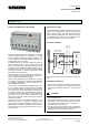
Figure 1: Location of operating and display elements
A1 LED for indicating normal operating mode (LED off)
and addressing mode (LED on); upon receiving the
physical address the device automatically returns to
normal operating mode
A2 Learning button for switching between normal op-
erating mode and addressing mode
A3 bus connection block, screw-less
A4 screw terminals for connecting the control circuits
A5 Slide switches for manual operation and for display-
ing the switching position per channel.
Slide in upper position: relay contact open (OFF)
Slide in lower position: relay contact closed (ON)
A6 mains connection blocks (screw terminals) for
connecting load circuits
Important note:
Manual operation is for emergency operation only and
not affecting the application program. No telegram is
sent on the bus, and the new switching status is un-
known to the software.
At bus voltage failure / recovery a previously manually
operated relay will also be set automatically to the con-
figured position.
Mounting and wiring
General description
The N-system DIN-rail mounted device (8 MU) can be
inserted to N-system distribution boards, either surface-
or flush mounted and wherever rails TH35-7.5 according
to EN 60715 are available.
Bus connection
The connection to the bus line is carried out via a bus
terminal block or by clicking the device onto a DIN-rail
(with a data-rail installed). Take care that the type plates
of all devices on a DIN-rail can be read in the same di-
rection, guaranteeing the devices are polarised correctly.
If the connection is established via a bus connection
block (data-rail not installed) the contacting system to-
wards the data-rail has to be covered by removing the
guide top e.g. with a screw-driver and afterwards snap-
ping on the insulation top to ensure a sufficient insulation
towards the DIN-rail (see figure 2).
When mounting the switching/dimming actuator
N 526E02 onto a DIN-rail with stuck-in data-rail (even in
combination with other DIN-rail devices) the usually em-
ployed bus line connector is not necessary. The bus
voltage is forwarded within the device from the bus con-
nection block to the data-rail pressure contacts of the
N 526E02.
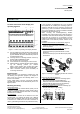
Installation of the DIN-rail mounted device
(
Figure 2
)
- Hang the device (B1) into the DIN-rail (B2) and
- rotate the device downwards until the slide bar audibly
clicks into position.
Dismantling the DIN-rail mounted device (Figure 2)
- Remove all connected cables,
- press the slide bar (C3) downwards with a screw-
driver and
- remove the device (C1) from the DIN-rail (C2) with a
swivel action.
B1
C1
C2
C3
B2
Figure 2: Installing and dismantling the DIN-rail mounted
device
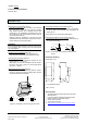
Removing the guide top
(Figure 3)
- The guide top (D3) encloses the contacting system
(D2) on the back side of the N 526E02 (D1)
- Insert the screw-driver between the N 526E02 (D1)
and the guide top (D3) and pull out the guide top.
Snapping on the insulation top (Figure 3)
- Stick the insulation top (D4) onto the contacting sys-
tem (D2) and snap it on by pressing.
D4D1 D1D3 D2 D2
Figure 3: Covering the contacting system