
Data Sheet for Product

GAMMA instabus
Technical Product Information
February 2007
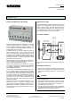
Switching/Dimming Actuator N 526E02 5WG1 526-1EB02
8x AC 230 V / 16 A
Technical manual N 526E02, 4 pages Siemens AG
Automation and Drives Group
Update: http://www.siemens.com/gamma © Siemens AG 2007 Electrical Installation Technology
Subject to change without prior notice P.O.Box 10 09 53, D-93009 Regensburg
2.5.1.12/4
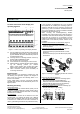
Removing the bus terminal
(Figure 4)
- The bus terminal block (E1) consists of two sections
(E1.1 and E1.2), each with four terminal contacts.
Care should be taken not to damage the two test
sockets (E1.3) by accidentally connecting them to the
bus conductor or with the screwdriver (when trying to
remove the bus terminal ).
- Carefully insert the screwdriver in the wire entry slot
underneath the bus terminal (E1) and pull the bus ter-
minal forwards out of the device (E2).
CAUTION
Care should be taken as there is a risk of to short circuit
the bus voltage when removing the bus terminal block
with a screwdriver.
Plugging in the bus terminal
(Figure 4)
- Place the bus terminal (E1) to the guide slot and
- push the device backwards until it reaches the stop.
Connecting the bus cable (Figure 4)
- The bus terminal (E1) is suitable for single core con-
ductors with 0.6 ... 0.8 mm Ø.
- Strip approx. 5 mm of the insulation from the conduc-
tors (E1.4) and plug in them into the terminal block
(E1) (red = +, black = -).
Disconnecting the bus cable (Figure 4)
- Remove the bus terminal block (E1) and the conduc-
tors (E1.4) of the bus cable by rotating them simulta-
neously backwards and forwards.
E2
E1
E1
E1.4
5 mm
E1
E1.4
E1.1
E1.2
E1
E1.3
Figure 4: Connecting, disconnecting the bus cable
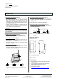
Connecting load and control circuits
(Figure 5)
- Strip approx. 8 … 9 mm of insulation from the conduc-
tor (F1.1], plug in the terminals (F1) and tighten the
screws (F1.2).
Cross sections: see “Technical specifications”.
Disconnecting load and control circuits (Figure 5)
- Loosen the screw (G1.2) and pull the conductor (G1.1)
out of the terminal (G1).
F1.1
F1.2
8 ... 9 mm
F1
G1.1
G1.2
G1
Figure 5: Connecting, disconnecting load and control
circuits
Dimension drawing
Dimensions in mm
b
90
44
55
45
b = 8 module units (MU)
1 MU = 18 mm
General notes
• Any faulty device should be returned to the local
Siemens office.
• If you have further questions about the product,
please contact our Technical Support:
℡ +49 (0) 180 50 50-222
" +49 (0) 180 50 50-223
! www.siemens.com/automation/support-request