
Data Sheet for Product
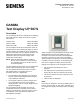
Table Of Contents

Technical Specification Sheet
Document No. 154-104
November 20, 2012
Siemens Industry, Inc.
Page 1 of 3
GAMMA
Text Display UP 587/1
Description
The Text Display UP 587/1 is available in the following
colors that match the design of the DELTA i-system
wall switches:
Titanium white 5WG1 587-2AB11
Carbon metallic 5WG1 587-2AB21
Aluminum metallic 5WG1 587-2AB31
The Text Display UP 587 and a DELTA line frame are
snapped onto the Bus Coupling Unit (BTM) UP 117/11.
The Bus Coupling Unit (BTM) UP 117/11 provides the
KNX bus connection to the Text Display UP 587/1. The
abbreviation BTM indicates that this type of BCU
provides the KNX bus connection through a Bus
Transceiver Interface (BTI).
NOTE: While the BTM looks similar to the BCU1,
devices, such as switches or motion sensors,
are compatible with one or the other and are
not interchangeable.
The Bus Coupling Unit and frame are not included and
must be ordered separately (see current catalog).
The Text Display UP587 has three pairs of horizon-
tally aligned buttons. Two display rows of 11
characters each form a display field.
• The top display field is assigned to the top pair of
buttons, and the second display field is assigned
to the middle pair of buttons.
• The third pair of buttons is used to navigate from
one function block to the next, select the text
display functions, and set contrast, brightness and
background lighting.
The Text Display UP 587 provides up to nine (9)
configurable functions for switching, forced-control,
dimming, solar protection, and scene control, as well
as the display of text, operational messages and
warning/alarm messages.
Alarm messages are accompanied by an alarm sound.
Warning/alarm messages only display if an alert
message is received. If more than one warning/alarm
message is received, the most recent one displays.
Alarm messages have priority over warning messages.
In addition to the nine functions, the Text Display UP
587 can be configured to display the date and time.
Display of the functions can be configured such that:
• The last function operated by the user is
displayed.
• The display shows a preselected function after a
timeout after the last user operation has expired.
• The function with the most recent change of value
is presented.
• Time and date are displayed.
LEDs
Four LEDs are assigned to the top and middle pairs of
buttons. Functions with an LED status indication may
be configured to display a statically lit and/or a flashing
LED.