
Data Sheet for Product

instabus EIB
Technical Product Information
September 2001
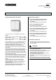
Push button AP 115 5WG1 115-3AB_1
Technical data
Power supply
via the bus line
Operating elements
1 learning button (combined with the display LED):
for toggling between normal mode/addressing mode
Display elements
• 1 red display LED (combined with the learning button):
for checking the bus voltage and for displaying normal
mode/addressing mode
• 2 red LEDs (always switched together):
as an orientation light or for status display (selectable),
only advisable for 1-fold push button AP 115 with
window
Connections
• Bus line: screwless bus terminal
0.6 ... 0.8 mm ∅ single core
Mechanical data
• Housing: plastic housing
• Dimensions (L x W x D): 75 x 66 x 52 mm
• Weight: approx. 120 g
• Fire load: approx. 2500 kJ ± 10 %
• Installation:
- surface-mounted, fixing drill holes:
4.5 mm ∅ drill template supplied
- cable entry for the bus cable via sliding nipple
Electrical safety
• Pollution degree (according to IEC 664-1): 2
• Type of protection (according to EN 60529): IP 44
• Protection class (according to IEC 1140): III
• Overvoltage category (according to IEC 664-1): III
• Bus: safety extra-low voltage SELV DC 24 V
• Device complies with
EN 50090-2-2 and IEC 664-1: 1992
Reliability
Failure rate: 254 fit for 40 °C (switch position)
262 fit for 40 °C (neutral position)
EMC requirements
complies with EN 50081-1, EN 50082-2 and
EN 50090-2-2
Environmental conditions
• Climatic withstand capability: EN 50090-2-2
• Ambient operating temperature: - 5 ... + 45 °C
• Storage temperature: - 25 ... + 70 °C
• Relative humidity (not condensing): 5 % to 93 %
Approval
EIB-certified
CE mark
in accordance with the EMC guideline (residential and
functional buildings) and the low voltage guideline
Location and function of the operating and
display elements
A6
A1
A2
A3
A4
A5
A6
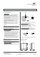
Diagram 1: Location of the display and
operating elements
A1 Housing
A2 Bus coupling unit
A3 Learning button for toggling between normal mode
and addressing mode for transferring the physical
address. It is combined with an LED for displaying
the normal mode (LED off) or addressing mode
(LED on); it is extinguished automatically once the
physical address has been transferred.
A4 Single or twin operating lever (depending on the
design) for plugging in the rockers
A5 LEDs as an orientation light or for status display
(only visible externally for 1-fold push button with
window)
A6 Sliding nipple for cable entry
Technical Manual AP 115, 4 pages Siemens AG
Automation and Drives Group
Update: http://www.siemens.de/installationstechnik Siemens AG 2001 Electrical Installation Technology
Subject to change without prior notice P.O.Box 10 09 53, D-93009 Regensburg
2.16.1.1/2