
Data Sheet for Product

instabus EIB
Technical Product Information
September 2001
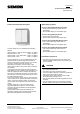
Push button AP 115 5WG1 115-3AB_1
Mounting and wiring
General description
The push buttons AP 115 are surface mounted using
screws. All the components (housing, rocker(s), bus
coupling unit) are supplied already assembled and
screwed together using the relevant screws. The screws
are only loosely screwed in and can be accessed by
removing the rocker(s).
Once the housing has been mounted for example on the
wall, the bus cable is fed into the housing through the
sliding nipple and wired accordingly.
The device is connected to the bus line via the bus
terminal 193 (screwless plug-in terminals for single core
conductors).
The rocker mount (dark grey frame) is then screwed in
place using the screws supplied and the rocker(s) is
clipped on.
Note:
Siemens AG AP 115, 4 pages Technical manual
Once the rocker mount has been screwed together, the
learning button is no longer accessible i.e. the physical
address should be set beforehand.
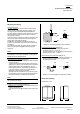
Removing the bus terminal
(Diagram 2)
- The bus terminal (B2) is located at the back of the bus
coupling unit (B1).
The bus terminal (terminal block) (B2) consists of two
sections (B2.1, B2.2), each with four terminal contacts.
Care should be taken not to damage the two test
sockets (B2.3) either by accidentally connecting them
to the bus conductor or with the screwdriver when
attempting to remove the bus terminal.
- Carefully insert the screwdriver in the wire entry slot in
the grey section of the bus terminal (B2.2) and remove
the bus terminal (B1) in the direction of the arrows.
Note
Do not lift the bus terminal out sideways as there is a
risk of shorting the device.
Plugging in the bus terminal (Diagram 2)
- Place the bus terminal (B2) in the guide slot of the bus
coupling unit (B1) and
- press the bus terminal (B2) inwards until it reaches the
stop.
B
2
.
3
B2
.
1B2
.
2
B
2
B
1
B2
Diagram 2: Removing/plugging in the bus terminal
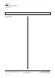
Connecting the bus cable
(Diagram 3)
- The bus terminal (C1) is suitable for single core
conductors with 0.6... 0.8 mm Ø.
- Strip the insulation from the conductor (C2) and plug in
the terminal (C1) (red = +, black = -)
Disconnecting the bus terminal
(Diagram 3)
- Remove the bus terminal (C1) and the conductor (C2)
of the bus cable by rotating them simultaneously
backwards and forwards.
5 mm
C1
C2
C1
C2
Diagram 3: Connecting/disconnecting the bus cables
Dimension drawing
Dimensions in mm
75
66
52
Automation and Drives Group
Electrical Installation Technology Siemens2001 Update: http://www.siemens.de/installationstechnik
P.O.Box 10 09 53, D-93009 Regensburg Subject to change without prior notice
2.16.1.1/3