
Data Sheet for Product

GAMMA wave
Technical Product Information
September 2007
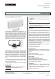
Door/window contact wave AP 260 titanium white 5WG3 260-3AB11
brown 5WG3 260-3AB81
Siemens AG wave AP 260, 4 pages Technical Manual
Automation and Drives Group
Electrical Installation Technology © Siemens AG 2007 Update: http://www.siemens.de/gamma
P.O. Box 10 09 53, D-93009 Regensburg Subject to change without prior notice
2.20.3.1/3
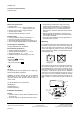
Before clipping the radio-controlled sensor onto the
mounting plate,
the insulating strip (D4) that is inserted in
the battery compartment (D1) on the back of the sensor
must be removed and if necessary an external window
contact should be connected.
D1
D2
D4
D5
D3
Diagram D
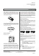
First the radio-controlled sensor (E1), as shown in Diagram
E, must be placed onto the mounting plate (E2). Then
you should slide it in the direction of the arrow until the
clamps (E3) click into place.
1
E1
E2E3
2.
1.
Diagram E
Dimension Diagram
Dimensions in mm
27
32
36
87 72
Connection of an External Window Contact
A conventional door/window contact (with a reed contact
which must be closed when the door or window is
closed) can be connected to the door/window contact
wave via plug-in terminals (D3) on the rear of the radio-
controlled sensor. This enables for example the cost-
effective monitoring of both doors in the case of a double
door.
The external reed contact is switched electrically in se-
ries to the reed contact in the radio-controlled sensor. In
the case of a double door, this means for example that
the opening of only one door is already detected and re-
ported, but it is not possible to determine which door has
been opened. The door is only detected and reported as
closed once both doors have been closed.
Note: The cable for connecting an external window con-
tact must not exceed 10 m.
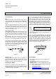
Monitor internal contact only
Diagram F1 indicates the plug-in terminals of the
door/window contact in the supplied state. It has been
set via the wire jumper between terminals 3 and 4 that
only the internal contact is monitored.
Monitor external contact only
Diagram F2 indicates the terminal assignment when only
an external contact should be monitored. The internal
contact has been deactivated via the wire jumper be-
tween terminals 1 and 2.
Monitor internal and external contact
Diagram F3 indicates the terminal assignment if the in-
ternal and an external contact should be monitored to-
gether. The wire jumper is omitted in this case.
Diagram F1 Diagram F2 Diagram F3
Strain relief
The cable can be fixed to the external contact via the
supplied clamping plate (D5). The maximum permitted
diameter of the connecting cable is 5 mm.
Location and Function of the Display and Op-
erating Elements
Diagram A
A1 LED for displaying the sending of a radio tele-
gram, the link with other radio-controlled compo-
nents and a low battery
A2 Push button for linking the door/window contact
with other radio-controlled components
Diagram D
D1 Battery compartment
D2 Battery
D3 Plug-in terminals for setting whether an external
contact should be monitored as well as for the
connection of an external contact
1 2
3
4 12
3
4 1 2
3
4