
Data Sheet for Product

GAMMA wave
Technical Product Information
September 2007
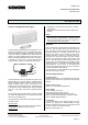
Door/window contact wave AP 260 titanium white 5WG3 260-3AB11
brown 5WG3 260-3AB81
Technical Manual wave AP 260, 4 pages Siemens AG
Automation and Drives Group
Update: http://www.siemens.de/gamma © Siemens AG 2007 Electrical Installation Technology
Subject to change without prior notice P.O. Box 10 09 53, D-93009 Regensburg
2.20.3.1/4
Commissioning
Note
When commissioning the door/window contact wave, it
must be linked via "learning telegrams" to the KNX radio-
controlled devices which should process its radio tele-
grams.
Only those radio-controlled devices which are able to
process the special door/window status message can be
connected to a door/window contact. These are, for ex-
ample, the push button wave shutter UP 211 and the
coupler wave/instabus UP 140.
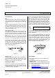
Connection via radio
To link (teach in) a door/window contact wave (G1) to a
push button wave shutter (G2), the push button wave
shutter must first be switched to the special function (re-
fer to the operating and mounting instructions of the de-
vice).
The push button (A2) on the door/window contact must
then be pressed for approx. 1 s. The LED (A1) flashes
for approx. 3 s if the learning telegrams have been sent.
You can now open and close the door or window to
check whether the door/window contact sends a radio
message each time door or window is opened and
closed (LED A1 illuminates briefly) and whether the radio
messages from the associated device are being cor-
rectly received and processed.
G2
G1
Diagram G
Deleting a link
Should an indoctrinated device cease to respond to a
given door/window contact, then the radio link is to be
deleted, i.e. it must be learned in again. The procedure
for deleting a link is exactly as for connecting.
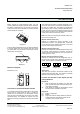
Replacing the Battery
The LED (A1) indicates that the battery needs to be re-
placed by flashing briefly every 10 s. In order to be able
to replace the battery, the radio-controlled sensor must
be removed from its mounting plate.
To do so, the lug (H3) must be pressed down with a tool
(e.g. a small screwdriver (H4)) in the gap between the
radio-controlled sensor (H1) and the mounting plate
(H2). You should then slide the radio-controlled sensor
(H1) to the left over the lug and out of its clamps (H5).
The battery compartment (D1) is located on the under-
side of the radio-controlled sensor. Its housing does not
need to be opened to replace the battery. The correct
polarity should be observed when replacing the battery.
Once the battery has been replaced, the radio-controlled
sensor must be placed onto the mounting plate again, as
shown in Diagram E.
Finally, it should be tested by opening and closing the
door or window whether the door/window contact wave
sends radio telegrams each time the door or window is
opened and closed (LED A1 lights up briefly) and
whether the radio telegrams have been received and
processed correctly from the associated device. The
LED (A1) should also have stopped flashing at cyclic in-
tervals to indicate that the battery is low.
1.
2.
H3
H5
H2
H1
H4
Diagram H
General Notes
• The operating instructions should be handed over to
the customer.
• Any faulty devices should be returned to the local
SIEMENS office.
• Should you have any further queries about this prod-
uct, please contact our Technical Support Department:
℡ +49 (0) 180 50 50-222
" +49 (0) 180 50 50-223
! adsupport@siemens.com
h www.siemens.de/automation/support-request
The used battery must be disposed of in
accordance with the applicable regulations.