
Data Sheet for Product
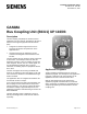

Table Of Contents

Technical Specification Sheet
Document No. 154-096
November 14, 2012
Siemens Industry, Inc.
Page 1 of 2
GAMMA
Bus Coupling Unit (BCU1) UP 110/03
Description
The Bus Coupling Unit (BCU) UP 110/03 connects
application units (for example, Push Button UP 245) to
the bus line through the physical external interface
(PEI).
• Telegrams received through the bus line are
processed by the BCU and passed on to the
application unit.
• Signals coming from the application unit are
converted into telegrams and transmitted to the
bus line.
The Bus Coupling Unit UP 110/03 is directly connected
to the bus line. It constantly monitors the bus and
determines if the line is clear for sending or busy with
other telegrams. Events, such as a switch signal, are
sent immediately provided the bus is not busy.
Otherwise, the sending request is postponed until the
line is clear.
The BCU is designed for mounting on NEMA wall
boxes or for attaching to data rings directly in the wall.
The connection to the bus line is established through
the Bus Terminal.
The application units are snapped onto the BCU and
secured with screws or clamps.
If it is connected to the bus with reversed polarity, the
Bus Coupling Unit UP 110/03 switches off (reverse
voltage protection). If the bus line voltage falls below
the minimum voltage of approximately 21 Vdc, the
application parameters and addressing is saved to the
BCU's EEPROM.
The BCU mounting frame is designed to accept a
DELTA profil design frame, which must be ordered
separately.
Application Programs
The Bus Coupling Unit (BTM) does not require an
application program. The description of the application
programs is included in the documentation for the
application unit that is connected to the BCU.
With the ETS (Engineering Tool Software) the
application program associated with the connected
device is selected, its parameters and addresses are
assigned appropriately and downloaded to the Bus
Coupling Unit.