
User Manual

Lighting
Switch/dimming actuators
3
■
Technical data
■
Selection and ordering data (06/2013)
Type Description
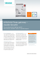
N 141/31 N 141/31 KNX/DALI Gateway Twin
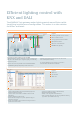
• Communication via KNX EIB with electronic ballasts (ECG) with
a DALI interface
• Two (2) DALI output acc. to IEC 60929, each for communication
with up to 64 DALI ballasts and at least 10 sensors
• Integrated power supply with input voltage
AC 110...240 V, 50/60 Hz or DC 120...240 V for powering the
gateway electronics and DALI output
• Maximum DALI output voltage of 19 V, short circuit resistant
• LC display for displaying operation mode and error messages
• Pushbutton for switching between bus and direct operating
mode
• Push buttons for switching On/Off of all connected DALI
ballasts
• One LED per DALI output for status signal of all connected
luminaries in direct mode
• Configurable assignment of max. 128 DALI ECG to max.
32 DALI groups, exclusive controlled in groups (switching,
dimming, set dimming value) and feedback for group status
and lamp failure
• Configurable behaviour for bus failure (stand-alone mode)
• Control (switching, dimming, set dimming value) of all con-
nected luminaries together in broadcast mode
• Status signal and display of lamp and ECG failure per group
and per DALI device
• Transformation of dimming commands into a temporary set
point adjustment for ballasts with integrated constant light
level control and directly connected light level sensor
• One or two level timer
• Integrated scene control for up to 32 scenes
• 16 integrated 2-level-controller for brightness control
• Assignment of DALI ECG to groups and test option for ECG,
groups and scenes via ETS during commissioning
• Assignment of DALI sensors and test option of sensors via
ETS during commissioning
• Integrated bus coupling unit with only half a standard bus
load
• Bus connection via bus terminal
• For mounting on DIN rail EN 60715-TH35-7.5, Width 4 MW
(1 Modular Width = 18 mm)
Accessories
DALI quadruple pushbutton interfaces
• Binary input device
• 4 inputs to connect installation buttons
• Supported actions per input
- Short button press
- Long button press
• Integrated DALI bus coupling unit for communicating with a
central DALI controller
• Power supply through DALI line with 6 mA DALI bus load
• For flush-mounting wall or ceiling outlet installations with a
60 mm diameter and depth of 60 mm
• Plug-in terminals for connecting the DALI line
• Cable set for connecting pushbuttons
DALI multi sensors for offices
• Used as passive infrared detector for indoor ceiling installation
- Sensing range, horizontal 360 °, vertical approx. 80 °
- For monitoring an area with a diameter of approx. 4 m to
approx. 7 m (depending on mounting and room height)
- LED on sensor head for display
• Used as brightness sensor
- cone–shaped detection area, opening angle 90 °
- measuring range 20 lx to 1000 lx
• Integrated DALI bus coupling unit for communicating with a
central DALI controller
• Power supply through DALI line with 5 mA DALI bus load
• Plug-in terminals for connecting the DALI line
• For installation in suspended ceilings
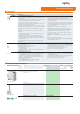
Type Version DT Order No. PU PS*/
P. u n i t
Weight
per PU
approx.
Unit(s) Unit(s) kg
5WG1141-1AB31
N 141/31 N 141/31 KNX/DALI Gateway Twin A 5WG1141-1AB31 1 1 0,470
Broadcast, 32 groups, 32 scenes,
DALI-sensors
Accessories
5WG1141-2AB71
DALI quadruple pushbutton interfaces A 5WG1141-2AB71 1 1 0,040
5WG1141-2AB51
DALI multi sensors for offices A 5WG1141-2AB51 1 1 0,11
PI_DALI_Gateway_EN.fm Seite 2 Mittwoch, 19. Juni 2013 10:49 10