
Data Sheet for Product


instabus EIB
Technical product information
October 2017
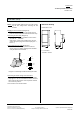
Thermal drive actuator N 605 5WG1 605-1AB01
(6 x AC 230 V / 0,05 A)
Siemens AG N 605, 6 pages Technical manual
Automation and Drives Group
Electrical Installation Technology Siemens AG 2017 Update: http://www.siemens.de/gamma
P.O. Box 10 09 53, D-93009 Regensburg Subject to change without further notice
2.8.1.2/1
Product and functional description
The thermal drive actuator N 605 has been specially de-
veloped to control miniature valves with electrothermal
valve drives for AC 230 V operating voltage. It is a DIN
rail mounted component for the instabus EIB. All the ca-
ble connections are carried out via screw terminals ex-
cept for the bus cable which is plugged in.
6 channels with semiconductor outputs are available to
control the valve drives. The outputs each have 2 output
terminals available (for N and switched L). A maximum
of 4 thermal drives may be connected in parallel to one
channel (actuator output). The outputs are monitored for
short circuits and overload. If a short circuit or overload
is detected, all the outputs are temporarily de-energized
and the red LEDs are triggered with a circulating light.
After a cooling down period of 6 minutes, the individual
outputs are switched on in sequence to determine where
the short circuit or overload has occurred. It is reported
via a special communication object which outputs are
affected. These outputs are disabled for further opera-
tion and the associated red LEDs flash rapidly. All the
other outputs are then operated as normal. It is only
possible to reset a disabled channel by isolating the ac-
tuator from the mains voltage.
The power supply of the actuator electronics is carried
out via an integrated power supply unit which is inde-
pendent of the EIB bus voltage. Each output in a group
of three outputs (outputs 1-3 or outputs 4-6) can be
manually switched on or off or to the 50% open position
via three push buttons which are integrated in the actua-
tor and each have 1 red LED. The manual switching also
functions if the bus cable is not connected or if the bus
communication fails. After a long push button action (> 2
s), the other valve group is selected. The yellow LED
indicates which of the two output groups can be oper-
ated (continuous light = outputs 1-3, flashing light = out-
puts 4-6).
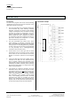
Application Program
21 A6 Actuator Heat/Cool Binary 906101
The application program enables the actuator outputs to
be controlled via ON/OFF switching commands or via
positioning commands expressed as a percentage. The
latter are converted into switching commands with pulse
width modulation under consideration of the heating up
and cooling down periods of a thermal drive. A changed
status or the current state of an output can be queried
via a separate status object or sent automatically. The
type of the output status object is always the same as
the trigger object. The behaviour of the actuator on bus
voltage failure can also be preselected (no action, switch
on, switch off, forced position).
If the program function “Calcification protection” is acti-
vated, each actuator output is switched on and off once
within a period of 6 days to prevent the valves from be-
ing fixed in position outside the heating respectively
cooling period.
If you do not want that, in a room with several windows,
the opening of only one window will switch the room
thermostat to the building protection mode, hereby clos-
ing all heating and cooling valves, then the program
function “Constrained Position” has to be activated. In
this case, only the valve of the respective radiator or
cooling ceiling element that is located in the immediate
vicinity of the opened window is closed, except for a set
residual opening (the “constrained position”). If a logical
connection of the “Constrained Position” object with the
“Frost alarm” or “Outside temperature” object is selected
and a frost alarm is not present or the outside tempera-
ture is > 1°C, the valve will be fully closed (and not set to
the constrained position) if the “Constrained Position”
object is set to logical 1 by the opening of a window.
There are 6 additional binary inputs available for floating
signal contacts in order to record and transmit the
switching state e.g. of the window contacts or dew point
detectors.