
Product Overview


GBB/GIB Series NSR Rotary 24 Vac - Modulating Control Technical Instructions
Document Number 155-176P25
December 15, 2004
Mechanical Range
Adjustment,
Continued
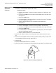
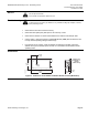
3. Return the actuator gear train to the "0" position using the steps that follow for the
clockwise or counterclockwise damper shaft rotation.
Clockwise-to-open:
a. Insert the shaft adapter to the right as close as possible to the raised stop. See
Figure 22.
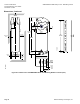
b. Hold down the PUSH button and rotate the shaft adapter to the left until it stops.
See Figure 23.
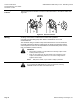
c. Release the PUSH button.
d. If the shaft adapter is not resting against the left raised stop, remove the adapter
and insert it against the left stop.
e. Place the position indicator to the "0" position on the outside scale.
See Figure 24.
Counterclockwise-to-open:
a. Insert the shaft adapter to the left as close as possible to the raised stop.
b. Hold down the PUSH button and rotate the shaft adapter to the right until it stops.
c. Release the PUSH button.
d. If the shaft adapter is not resting against the right raised stop, remove the adapter
and insert it against the right stop.
e. Place the position indicator to "0" on the inside scale.
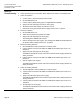
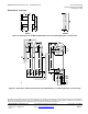
4. Determine the angle of rotation for the damper blade shaft. Subtract that amount from
90°.
5. Remove the shaft adapter and insert it with the position indicator pointing to mark on the
scale calculated in the previous step. See Figure 25.
6. Attach the clip.
7. Rotate the damper blade shaft to its "0" position.
8. Return the actuator to the damper shaft and tighten the shaft adapter to the damper shaft.
90
90
EA0651R1
PUSH
A
N
G
L
E
O
F
R
O
T
A
T
I
O
N
Figure 25. Mechanical Range Adjustment.
Siemens Building Technologies, Inc. Page 11