
Product Overview


Technical Instructions GBB/GIB Series NSR Rotary 24 Vac - Modulating Control
Document Number 155-176P25
December 15, 2004
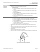
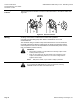
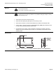
Reversing the Position
Indicator
Reverse the position indicator so that the counterclockwise 0 to 90 scale is visible. See
Figure 26.
Figure 26. Position Indicator.
Wiring
All wiring must conform to NEC and local codes and regulations.
Use earth ground isolating step-down Class 2 transformers. Do not use
autotransformers.
The maximum rating for a Class 2 step-down transformer is 100 VA. Determine
the supply transformer rating by summing the VA ratings of all actuators and all
other components used. It is recommended that one transformer power no more
than 10 actuators (or 80% of its VA).
WARNINGS:
• Mixed switch operation is not permitted to the switching outputs of both
auxiliary switches (A and B).
• Either AC line voltage from the same phase must be applied to all six
outputs of the dual auxiliary switches, or UL-Class 2 voltage must be
applied to all six output.
NOTE: With plenum cables, only UL-Class 2 voltage is permitted.
CAUTION:
Do not parallel wire GBB/GIB with any other type of actuator, including
GBB/GIB actuators with date codes earlier than 501
.
EA0551R2
POSITION
INDICATOR
1
2
3
PUSH
PUSH
Page 12 Siemens Building Technologies, Inc.