Installation Manual Edition 8/2007 MAXUMTM edition II Process Gas Chromatograph pro ces s p GAS CHROMATOGRAPHY
Maxum™ edition II Process Gas Chromatograph Table of Contents Getting Help Safety Practices & Precautions Site Considerations Maxum II Specifications Maxum II Outline Drawing Receiving a Crated Analyzer Mounting the Analyzer Cable Connection Installing Primary AC Power Utility Gas Supply Installation Sampling System Installation Analyzer Connections Maxum II Initial Startup Procedures Maxum II Shutdown, Restart, and Cleaning Procedures Assigning IP & Sub Network Mask Addresses Spare Parts Siemens © 2001-2
Getting Help Contacts for Help Siemens provides support for the Maxum System worldwide. Contact information is provided on all Siemens products at the web sites noted below. This page provides contact information for Maxum System technical support, training, spare parts, and field service callout. Worldwide e-mail requests can be submitted 24 hours a day, 7 days a week. Service contracts can be established for direct remote phone service for products or for regular field service visits to the site.
Safety Practices and Precautions Safety First This product has been designed, tested, and supplied in a safe condition in accordance with IEC Publication 61010-1, Safety Requirements for Electrical Equipment for Measurement, Control, and Laboratory Use - Part 1: General Requirements. This manual contains information and warnings, which have to be followed to ensure safe operation and to maintain the product in a safe condition.
Safety Practices and Precautions, Continued Hazardous or Poisonous Gases When hazardous gases (such as poisonous, flammable, or oxygen depleting) are potentially present in or around the Maxum edition II Process Gas Chromatograph (hereafter referred to as Maxum II) area, all national and international requirements must be fulfilled to protect personnel and the environment against hazards that could arise.
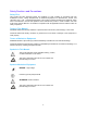
Site Considerations Description To protect the Maxum II from the elements, it should be located in an analyzer house or a similar protected enclosure; see Figure 1-1. The air temperature around the analyzer should be maintained between 0°F (-18°C) and 122°F (50°C). An installation drawing package will be sent out early in the project to document the application specific information for each Maxum II needed for site preparation. Final documentation will be shipped with the unit. Figure1-1.
Site Considerations, Continued When the Maxum II contains an air bath oven, it will vent in excess of 3 SCFM (85 liters per minute) of heated air through the oven exhaust. See note below for the recommended approach. WARNING All vent lines and oven exhaust should be vented outside the shelter. The vents should be connected to a location where the pressure is atmospheric.
Site Considerations, Continued Qualified Personnel Only suitably qualified personnel may operate or perform maintenance on the Maxum II. purposes of safety, qualified personnel are defined as follows: For the • Those who have been appropriately trained for the tasks which they are performing (for example, commissioning, maintenance, or operation). • Those who have been appropriately trained in the operation of automation technology equipment and are sufficiently acquainted with Maxum II documentation.
Maxum II Specifications The equipment is designed to be operated under normal environmental conditions unless noted otherwise in the specifications that follow. Configuration Oven Options Detector Modules Number of Detector Modules Sample/Column Valves Valveless Option Columns Gas Supply Regulation Solenoids Air bath: Single isothermal oven or split oven with 2 independent isothermal zones, or one isothermal and one PTGC Airless: Single or dual independent ovens.
Maxum II Specifications, Continued I/O Options Standard I/O Board Slots for Optional I/O I/O Boards Digital Inputs Digital Outputs Analog Inputs Analog Outputs Termination 2 analog outputs; 4 digital outputs (1 indicates system error, 3 are user configurable); 4 digital inputs; 1 serial output 2 AO 8: 8 electrically isolated analog output channels D I/O: 4 digital inputs and 4 digital outputs A I/O: 2 digital inputs and 2 digital outputs, 2 analog inputs and 2 analog outputs Optocoupler with internal 12
Maxum II Specifications, Continued Installation Configuration Single unit with multiple enclosures CAUTION When mounting the analyzer on a wall, care should be taken to ensure that the wall (vertical mounting surface) can withstand four times the minimum weight of the analyzer when mounted with the appropriate hardware. In some cases, it is recommended that brackets, such as Unistrut or angle iron be added to the mounting surface to help distribute the weight.
Maxum II Specifications, Continued AC Power Instrument Air Carrier Gas Flame Fuel Flame Air Corrosion Protection 100-130 VAC or 187-264 VAC (configuration dependent); 47-63 Hz., single phase Transient Overvoltage – Category II (IEC 60364-4-443) Single oven: 14 amperes maximum.
Maxum II Outline Drawing Notes Unless otherwise specified, dimensions are shown as millimeters (Inches) Recommended Minimum Clearances 2 3 Left Side - 460 (18”) Right Side – 460 (18”) Front Side – 654 (25 ¾”) Center to Center – 1120 (44”) For Air Bath Oven Only Left Exhaust For Single Oven Applications (1” Nipple) Left and Right Exhaust For Split Oven Applications (1” Nipple) 12
Installation Introduction This section is intended for installation personnel. After completing these procedures, the Maxum II will be ready for startup. To ensure a safe and trouble-free installation, follow all instructions and associated advisories. The Maxum II has special instructions in the custom documentation and on tags placed on the unit. These must be followed as well to ensure safe operation of the Maxum II.
Receiving a Crated Analyzer Instructions When the Maxum II is shipped to the installation site in a reinforced crate with vibration protection, it will be clearly labeled for horizontal placement and handling. On receipt of goods, look for any visible damage and verify that all items noted to be shipped were received. Record on the goods receipt any damage or missing items noting the item(s) and quantity missing on all copies.
Mounting the Analyzer Instructions The following procedures should be used to mount the Maxum II to wall or bulkhead; see Figure 2-1. Maxum II Outline Drawing on page 16. WARNING Prior to wall mounting and without the sampling system, the Maxum II will weigh a minimum of 170 pounds (77 kg). To mount the Maxum II to the wall, use a mechanical lift or the number of people specified in the user’s policy on lifting and installing.
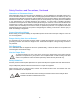
Mounting the Analyzer, Continued Refer to Application Drawing Package, Dimension Diagram Analyzer sheet for drilling information. The following diagram has typical information for mounting, and as shown in the example pattern below, drill 12 mounting holes in the shelter (16 if sample system is attached to Maxum II.) If using an M6 bolt, use a 5.10 mm (.201 inch) drill bit. If using ¼ x 20 bolts, use a No. 7 (.201) drill bit. If using ¼ x 28 bolts, use a No. 3 (.213) drill bit.
Cable Connections Protective Earth Ground Install protective earth ground per applicable codes (see diagram on page 16). This is located on the back of the Maxum II and is secured with a M5 x 10 socket head screw (uses M4 hex). Cable Connection using Steel Conduit System Using flexible conduit and/or armored cable is equivalent to using “steel conduit.” The power wiring and the Ethernet wiring can be regular unshielded lines.
Installing Primary AC Power Primary AC Power For Installation of AC Power for CE / ATEX units, refer to the Application Drawing Package, and page 17 concerning the special requirements for these systems which will be different from the information contained below. This section is documenting the requirements only for non-CE/ATEX units. The Maxum II operates from 100-130 VAC or 187-264 VAC 47-63Hz, single phase.
Installing Primary AC Power, Continued Circuit Breaker The circuit breaker should have the correct ampere rating, number of poles, and rated for the area that it will be installed. The circuit breaker must be installed in close proximity to the Maxum II so it is easily accessible to the service technician for turning power off to perform maintenance functions or for safety purposes. In addition, the circuit breaker must be labeled as the disconnecting device for the Maxum II.
Installing Primary AC Power, Continued Installation Procedure To install primary AC wiring, perform the following procedures: Shut off the primary AC power supply line to this location. Open the front door of the Electronic Enclosure (if locked, use a 4 mm Allen wrench to unlock it.) Install circuit breaker, conduit and primary AC wiring appropriate for the area safety classification. The breaker should be located near to the Maxum II.
Installing Primary AC Power, Continued Install AC power wiring to the PECM connectors TB1, TB2, and TB10 as specified in the Application Drawing Package, Block & Utility sheet. TB10 is used for AC input to power the electronics enclosure. In the standard configuration TB10 is connected to TB1. Optionally, TB10 may be isolated from TB1 and connected to a separate UPS as specified in the drawing package.
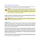
Installing Primary AC Power, Continued F1 F5 F2 F4 F3 Verify that the correct fuses are in place. Fuses are located on the PECM. See diagram below for correct placement. AC Power Circuit 1 Heater Channel 6 AC Power Circuit 2 LWH 1-5 (low wattage heaters) Power Supply (24V out) Fuses for 115VAC Fuses for 230VAC 16A 10A (1901693-001) (1901694-001) 6.3A 6.3A (1901695-001) (1901695-001) 16A 10A (1901693-001) (1901694-001) 10A 10A (1901694-001) (1901694-001) 3.15A 3.
Utility Gas Supply Installation Description This section provides the utility gas supply installation requirements for the analyzer. Carrier Supply Gas Calibration Standard Detector Fuel Supply Compressed Air Supply Refer to Application Drawing Package, Block Diagram Utility Connections sheet for analyzer requirements. WARNING Ensure that personnel, electrical, and local and national codes are considered for storage, use, and handling of compressed and liquefied gasses in portable cylinders.
Utility Gas Supply Installation, Continued Figure 2-4. Automatically Switched Carrier Gas Cylinders Calibration Standard Supply Installation The Calibration Standard Supply required is specified in the "Notes" block on the Block Diagram Utility Connections sheet contained in the Application Drawing Package. Mounting Always mount the calibration standard cylinder as close to the analyzer as practical. When installing calibration standard cylinders, always use new, clean, ¼” (.
Utility Gas Supply Installation, Continued Detector Flame Fuel Supply The FPD will need supplemental hydrogen and the FID may also need supplemental hydrogen for the flame depending upon the type of columns used. See Technical Specifications on page 11 for requirements for the flame fuel supply. If your analyzer uses a hydrogen carrier, it also serves as the flame fuel for a FID or an FPD. In this case, the flame fuel regulator may or may not be supplied.
Sampling System Installation Siemens Supplied Sample System The sampling system provides a conditioned process sample to the analyzer. This section is intended to provide guidelines and is not intended to be a comprehensive installation procedure. Be sure to follow local and national codes with regard to the installation of this equipment. If the sampling system was provided by Siemens, then references will be given to link to the custom documentation package.
Sampling System Installation, Continued Transport Tubing Refer to Application Drawing Package, Block Diagram Utility Connections sheet. Gas Samples Transport tubing is typically ¼“ (6.35 mm) OD for gas samples, and ⅜“ (9.53 mm) OD for liquids. Leave enough extra tubing to make sure it will reach the connection points. The stainless steel tubing must be very clean and dry. If in doubt, flush it with acetone and dry it with an inert gas. Cap the open tubing ends to prevent contamination.
Sampling System Installation, Continued Figure 2-4. Typical Installed Sample Probe Returning Samples to the Process Stream Refer to the Application Drawing Package, Sampling System sheet and Block Diagram Utility Connections sheet. If the sample stream is a gas and is to be released to the atmosphere, install a vent line outside the analyzer house to at least 8 ft. (2.4 m) above the ground. The exhaust end should be curved down, or a vent cap added for weather protection.
Sampling System Installation, Continued Liquid Samples If the sample stream is a liquid, all of the liquid flows should be returned to the process. It is easiest to return both the sample bypass and analyzer flows together; however, if the differential pressure available at the analyzer house is less than 10 psig (69 kPa), a separate power pressure return is required for the analyzer flow (typically 20 cm3/min.) If the liquid could reverse flow in the process line, install check valves where applicable.
Analyzer Connections Before You Begin Ensure that the Utility Gas Supply and Sample System are installed in accordance with the Utility Gas Supply Requirements on page 23 and the Sample System Installation requirements on page 26. Reference the Analyzer Connections below. Input/Output Lines If your system uses optional peripheral or control devices, additional wiring is required. Siemens recommends the wire specifications shown in the Application Drawings Package, Cable Specifications sheet.
Analyzer Connections, Continued For an analyzer with an FID, connect a length of new, clean, ¼” (6.35 mm) stainless steel tubing to the analyzer port labeled "FLAME AIR OUT," and run it to the inlet port on a separately mounted air treater. For an analyzer with an FID, connect a length of new, clean, ¼” (6.35 mm) stainless steel tubing to the instrument air supply, and run it to the outlet port on the separately mounted air treater. Mount the air treater in a convenient location near the analyzer.
Maxum II Initial Startup Procedures Important Before proceeding with these procedures make sure the Maxum II is installed correctly in accordance with these instructions and local and national codes. Refer to the custom documentation for particular Maxum II details and/or procedures. Instructions Perform all the procedures in this section consecutively starting with inspection of the Electronics Enclosure. WARNING When the Electronic Enclosure door is open, voltage dangerous to life exists.
Refer to the comments on Hazardous gases on page 3. Maxum II Initial Startup Procedures, Continued Continuing with the main power still off, open the oven door and carefully remove all material, if present. If columns were removed for shipment, these should be installed in the oven. Check for any crimped or broken tubing. Finger test fittings to make sure they are tight. Establish Utility Gas Flows Unblock the instrument air supply.
Maxum II Initial Startup Procedures, Continued Check Operation of Oven Heaters For Air Bath heaters (including PTGC) perform the following procedure: Note that on PTGC units, it is recommended to have carrier flow thru columns during this test. Turn heater circuit off by setting oven air regulator below 5 psig. Through the MMI, observe the oven temperature and set point temperature. Cool oven down, approximately 20 to 40 degrees below set point.
Maxum II Initial Startup Procedures, Continued Observe when the over temp shutdown light comes on. This is indicated when the fourth LED lights (red). Verify through the MMI that the oven temperature (or heated device) starts decreasing (this may take a few minutes). Also, that an over temp fault alarm is generated. If dual oven applications, repeat steps above for second heater channel.
Maxum II Initial Startup Procedures, Continued Prepare Flame Detectors If Present For FID and FPD detectors, disable carrier gas flows and check fuel and air flows. The flows must be measured separately. Leak check or adjust pressure setpoints if necessary. Record any changes in pressure setpoints for inclusion in the EZChrom method later. Ignite the detectors. The MMI in the EPC screen will include a Detector Manual Ignite entry in the list of digital outputs (valves, etc.
Maxum II Initial Startup Procedures, Continued If analyzer with the IP address entered in the Maxum II does not appear in the analyzer list at the bottom of the main screen in System Manager, add it manually via the menu, System > Add Unit; a dialog box will appear, enter the unit name, type and IP address, then click Add and the unit will be added to the analyzer list. Launch EZChrom on the workstation.
Maxum II Initial Startup Procedures, Continued At the end of the cycle, import the chromatogram: File > Data > Import. Compare the chromatogram to the factory chromatogram provided with the documentation. Pay particular attention to the peak retention times, valve timing and separation. Adjust valve times as necessary. If the retention times do not closely match factory documentation, first make sure the column oven has been equilibrated at operating temperature for at least two hours.
Maxum II Initial Startup Procedures, Continued Check for Proper Reporting of Results In the main System Manager screen, double click in the analyzer icon at the bottom of the screen to bring up the database tables. The analyzer name and IP address are located next to the analyzer icon. Press the “+“ next to the appropriate application, i.e., App 1, App 2, etc., to expand the list of tables. Double click on Tables to open an additional list of tables.
Maxum II Shutdown, Restart, and Cleaning Procedures Introduction The Maxum II is designed to automatically recover to full operation after a power fail. This process will take an amount of time depending upon the duration of power loss. It may be a few cycles to several cycles, depending upon cycle length, oven temperature, and a number of other factors. If the user wants to remove power for any reason, this can be done as simply as removing the power and then restoring it when desired.
Assigning IP & Sub Network Mask Addresses Overview All Maxum II units connected to a network must have a unique 32-bit IP and a common sub network mask (subnetmask) address. The subnetmask together with the IP address is used to define the logical network number of the device. The user must assign the addresses before the unit is network operational. Definitions IP Address. The IP address is a 32-bit address that defines each Maxum II’s network ID and host ID.
Spare Parts Spare Parts List Please refer to page 2 for information on where to order spare parts. Providing the unit serial number of the instrument will expedite the ordering process. Description Part Number (Siemens global) Part Number (Americas) Maxum II Fuse Kit GWK-AI2020151-001 2020151-001 The Recommended Spare Parts list contained in the custom Application Drawing Package contains a comprehensive spare parts list for the Maxum II.
8/2007 Edition 2000595-001 Siemens Energy & Automation, Inc. 7101 Hollister Road, Houston, TX 77040 United States Phone +1 (713) 939-7400 Fax +1 (713) 939-9050 www.usa.siemens.