
User Manual


3 / 10
A6V10636150_en--_c Siemens
2018-01-11 Building Technologies
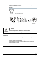
Position indication:
Electrical
Output voltage U = DC 0/2...10 V is
generated proportional to the rotary angle.
U depends on the rotary direction of the
DIL switch setting.
Self-adaptation of linear
span
When self-adaptation is active, the actuator
automatically determines the mechanical
end positions of the linear span.
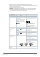
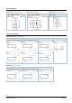
Manual adjustment The rotary actuator can be manually adjusted by pressing the gear train
disengagement button.
Rotary angle limitation The rotary angle of the shaft adapter can be limited mechanically with a set screw.
Technical design/mechanical design
Housing
The housing consists essentially of flame retardant, non brominated, non chlorinated glass
fibre reinforced plastic.
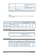
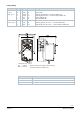
Type summary
Type Stock no. Control Operating
voltage
Positioning
signal Y
Position
indicator U =
DC 0…10 V ⎓
Self-adaption
of rotational
angle range
Aux.
switches
Rotary
direction
switch
GDB141.9E S55499-D200
Open-close or
three-position
AC 24 V ~ /
DC 24…48 V ⎓
‒ ‒ ‒ ‒
yes
GDB341.9E S55499-D201 AC 100…240 V ~
GDB161.9E S55499-D275 Modulating
AC 24 V ~ /
DC 24…48 V ⎓
DC 0/2...10 V ⎓ yes yes ‒
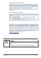
Accessories / Spare parts
Individual spare parts are not available. Components of the accessory kit ASK77.3
1)
,
available as an accessory, can however be used for spare parts.
Description Components
ASK77.3 Accessory Kit BV for GLBxx1.9E Mounting bracket (base plate)
Axle with sleeve and spring
Manual lever with locking clip
1)
Can also be used as rotary actuator for ball valves together with the actuator for air dampers G..B.1E.
Equipment combinations
GDB..9E and VA..61.. 2-port control ball valves
Control ball valves with:
G..B
k
vs
[m
3
/h] DN
GDB..9E
internal threads
1)
Rp external threads
2)
Χp
max
Χp
s
‒ ‒ VAG61.15.. G 1 B 1…6.3 15
350 1400
VAI61.15.. Rp ½“ ‒ ‒ 1…10 15
VAI61.20.. Rp ¾” VAG61.20.. G 1 ¼ B 4…10 20
VAI61.25.. Rp 1” VAG61.25.. G 1 ½ B 6.3…16 25