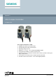
OpenAir™ VAV Compact Controller G..B181.1E/3 VAV compact controller 5 / 10 Nm ● ● ● ● ● ● ● ● CE1N3544en 2021-10-25 GDB181.1E/3 with 5 Nm nominal torque GLB181.
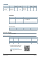
Type summary Type GDB181.1E/3 GLB181.1E/3 Stock no. Operating voltage Control / feedback signal 0…10 V BPZ:GDB181.1E/3 AC 24 V BPZ:GLB181.1E/3 1) Running 2) Holding or 2…10 V Power Runtime Manual adjuster Position feedback 150 s Yes Yes consumption 3 VA / 2.5 W 1) 1 VA / 0.
Product documentation Title Topic TM Document ID OpenAir VAV compact controller G..B181.1E/3, Technical Basics VAV modular controller ASV181.1E/3 P3544 Mounting instructions VAV compact controller Mounting and installation instructions M3544 Accessories and Spare Parts for Air Damper Actuators ASK.. Data sheet; accessories and spare parts for air damper actuators type GDB../GLB.. N4698 Related documents such as environmental declarations, CE declarations, etc.
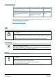
IP54 protection in the following mounting positions: Accessory mounting holes Maintenance ● ● The VAV compact controllers are maintenance-free. Disconnect the electrical connections from the terminals if you need to service the device. CAUTION Risk of injury from electric shock There is a risk of injury from electric shock when using the gear train disengagement slider to manually adjust the actuator. ● The actuator must be in a de-energized state during manual adjustments.
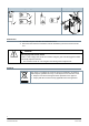
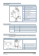
Device components and HMI (Human-Machine Interface) Device components 1 Shaft attachment screw 2 Set screw for rotation angle limitation 3 Gear train disengagement slider 4 6-core connecting cable (power and communications) 5 Connection nozzle for measuring differential pressure in the VAV box ("+": side with higher pressure) 6 Connection nozzle for measuring differential pressure in the VAV box 7 Configuration and maintenance interface (under cover) 8 LED 9 Rotation angle indicator LED co
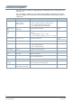
Commissioning and parametrization Parametrizing the VAV application The VAV compact controllers are parametrized via configuration tools, see Equipment combinations [▶ 2]. The VAV compact controllers are pre-configured by the OEM via the PPS2 interface (with AST20 or ACS931). Some parameters can be changed during commissioning, operation, or maintenance. Parameter Range Description Factory setting Operating mode CON (VAV operation) / 3P (pos.
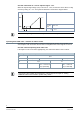
Operating modes Operating mode CON / VAV - variable air volume control Variable air volume control (VAV): The operating point is determined by the setpoint (DC 0…10 V or DC 2…10 V signal at YC input) and the Vmin / Vmax settings.
Override control with YC = 0 V for setpoint range 2…10 V When the setpoint signal range (YC) is set to DC 2…10 V, the actuator can be driven to "fully closed" by setting YC = 0 V. The hysteresis behavior is shown in the diagram below. Operating mode CON / VAV YC 2…10 V A full closure by setting YC = 0 V in 2-10 V operation overrides the inputs Y1 and Y2.
Operating mode 3P - open loop control To use VAV compact controllers as 3-position actuators with air volume flow measurement, the parameter "operating mode" must be set to "3P". In this operating mode, air volume flow control by the VAV compact controllers is deactivated and the parameters Vmin, Vmid, and Vmax have no effect. The damper opening direction is determined by the connection of signal inputs Y1 and Y2.
Technical data Power supply Operating voltage AC 24 V ± 20 % (SELV) or AC 24V class 2 (US) Frequency Power consumption 50 Hz / 60 Hz at 50 Hz Rotating 3 VA / 2.5 W Holding 1 VA / 0.5 W Function data Runtime for nominal rotation angle 90° Torque 150 s (50 Hz) / 125 s (60 Hz) Nominal Maximum Rotation angle GDB181.1E/3 5 Nm GLB181.1E/3 10 Nm GDB181.1E/3 <7 Nm GLB181.
Directives and standards Product standard EN 60730-x Product family standard EN 50491-3, EN 50491-5 General requirements for Home and Building Electronic Systems (HBES) and Building Automation and Control Systems (BACS) Electromagnetic compatibility (field of use) For residential, commercial and industrial environments EU conformity (CE) GDB181.1E/3 A5W00003842 1) GLB181.1E/3 A5W00000176 1) GDB181.1E/3 A5W00003843 1) GLB181.
Diagrams Internal diagram The VAV compact controllers are supplied with a pre-wired connecting cable. All interconnected devices must be connected to the same G0. Tool = Configuration and service interface (from Series E: use 7-pin plug) Cable designations No.
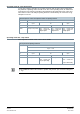
Connection diagrams CAUTION Device under voltage ● ● the operating voltage at terminals G and G0 must comply with the requirements for SELV or PELV. Safety transformers with double insulation as per EN 61558 are required; they must be designed for 100 % duty. Operating mode CON / VAV VAV (var. air volume flow) supply / extract air control N1 G..1B181.1E/3 N2 VAV room temperature controller / thermostat CAV (const. air volume flow) supply / extract air control N1 G..1B181.
Complete close-off with Y1/Y2 inputs N1 G..1B181.1E/3 S1 Window contact (Window closed – contact open) Operating mode 3P (Actuator) Supply / extract air control N1 G..B181.1E/3 (supply air) N2 G..B181.1E/3 (extract air) N3 Room temperature controller B1 Room unit N1 G..B181.
Dimensions Dimensions in mm Issued by Siemens Switzerland Ltd Smart Infrastructure Global Headquarters Theilerstrasse 1a CH-6300 Zug Tel. +41 58 724 2424 www.siemens.com/buildingtechnologies Document ID CE1N3544en Edition 2021-10-25 © Siemens Switzerland Ltd, 2005 Technical specifications and availability subject to change without notice.