
Product Overview


OpenAir GEB Non-Spring Return Rotary Electronic Damper Actuators Technical Instructions
Document Number 155-318P25
August 27, 2007
Siemens Building Technologies, Inc. Page 11
Control Signal
Adjustment, continued
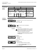
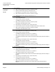
Uo = 2; ΔU = 16V
Umin = minimum control signal
Umax = maximum control signal
100
0
ΔU (16 V)
Y
U
(v)
Y
S
(%)
21810
U
min
U
max
50
U
o
EA0412R1
Figure 13. Example.
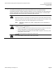
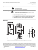
AB
-2,5 0 10 20 30 70 80 90 92,5
0 10 20 30 70 80
EA0640R1
92,5 90 80 70
60
20 10
-2,5
90
0
← Actuator scale: Clockwise
Adjustment range for switches A and B:
Setting interval: 5°
Switching hysteresis: 2°
← Actuator Scale: counterclockwise
Dual auxiliary switch
GEB164.1U,
GEB136.1U
To change the settings of A and B:
NOTE: The scale is only valid when the
actuator is in the "0" position on
clockwise motion.
• Use the adjustment tool provided
with the actuator to turn the
switch adjustment dials to the
desired signal setting.
Factory setting:
Switch A 5°
Switch B 85°
50
40
30
20
10
50
60
70
80
90
A
B
Aux Switch
Adjustment
EA0875R1
Figure 14. Dual Auxiliary Switch Dials.
.
NOTE: Use the long arm of the "†" to point to the position of switch A. Use the
narrower tab on the red ring to point to the position of switch B