
Specifications


GEMINI
2
Traffic Outstation Handbook
667/HB/32600/000 Page 103 Issue 11
The Power Supply operates from 85 to 265V AC, and therefore needs no external set-
up to operate from either 120 or 230V AC.
However the OMCU’s lamp monitor Zero Crossover circuit requires setting. This setting
is achieved by selecting the correct input connector socket on the High Voltage cable
form.
If 120V setting is required, change the setting as detailed, before applying mains. The
relevant connector socket positions for the 120V or 230V setting is described below.
Note that if OMCU lamp monitoring is not required, then the wires from the PSU can be
left unconnected since the female bullets have plastic covers that naturally insulate
them.
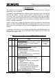
Cableform Position
Voltage Supply
PL2 pin 11
ZXO Mains Input (Mains Live)
PL2 pin 13
Neutral Return 120V Operation
PL2 pin 14
Neutral Return 230V Operation
Note 1: Before applying the mains’ power, recheck the correct voltage setting has been
selected and the Zero Crossover Mains’ Input (ZXO Mains I/P) has been
connected.
Note 2: Pins 11, 13 and 14 should be connected as shown on the first LMU I/O board
only. These pins should be left unconnected on the second and third boards
fitted to a unit.
If 120V operation is required then a different variant of the Voltage Monitor Transformer
must be used. The 100V Welsh Office version is 667/7/25172/500, see section 5.2.7. A
design for a 120V version would need to be requested.
9
10
11
12
13
14
Input Live
Neutral
120V
ZXO Mains
230V