
Specifications


GEMINI
2
Traffic Outstation Handbook
667/HB/32600/000 Page 151 Issue 11
9.6.1 Communicating Locally with the MOVA Unit
7)
9.6.1
Connect the PC to the MOVA unit’s local port (the 25 way D-type
connector on the front of the processor board) and start the MOVA
communications application.
Connect a normal controller handset cable (such as the IPT cable 667/1/17523/003)
from the PC to the 25 way port on the front of the MOVA unit. Also see Section 3.10.6.
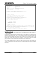
Start the MOVA Communications program, which can be downloaded from the TRL
website. The program will ask which PC COM port the serial cable is connected to.
It will then ask whether the MOVA unit is connected locally or remotely via a modem.
Select local communications and then press ‘Return’ until the unit responds.
If nothing is displayed, check that the cable has been connected to the correct serial
COM port and that no other applications on the PC are using the same serial port.
Connection is initially to the OMCU handset application. To connect through to the
MOVA application, simply enter ‘MOVA’ (or ‘XXM’).
Before the MOVA unit displays its main menu, it may display its current time and date. If
necessary, correct this using section 9.6.6 on page 155.
NB: If the Instation is communicating remotely with the MOVA unit, then access to
MOVA on site will be refused until the call is complete. Likewise, while an engineer
on site is connected to MOVA, remote communications from the Instation to
MOVA are refused. The Instation will have to try again later.
When ‘FI’ (Finish) is entered from the MOVA menu, the connection will return to the
OMCU handset application. The serial cable can now be safely disconnected from the
front of the MOVA unit and pressing F10 can close the MOVA Communications
application.