
Specifications


GEMINI
2
Traffic Outstation Handbook
667/HB/32600/000 Page 153 Issue 11
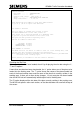
9.6.4 Serial Link between MOVA and an ST800/700 (MIO)
10)
9.6.4
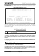
If MOVA is to use a Bus / MOVA (Digital) I/O Board, check that the
SOP handset command shows the correct type of I/O boards have
been detected, see page 249.
If MOVA is to use the enhanced serial link to an ST800/700 but the
OMCU has not been configured, enable the facility manually using
‘MIO=2’ and check that the enhanced serial link is active, i.e. ‘EEL:3’.
The Outstation has the option of using an enhanced serial link to an ST800/700 traffic
controller to monitor the traffic controller. Through this link the OMCU receives
information such as the detector and green states to provide a more integrated traffic
product and to remove the need for almost all of the Outstation’s external wiring.
This enhanced serial link can also be used by MOVA in the OMCU and MOVA unit.
Over this link MOVA obtains the states of all of its detectors and the stage/phase
confirms from the ST800/700 traffic controller and passes back the required force bits.
Note that the ST800/700 traffic controller must be configured to use ‘Serial MOVA’ for
this facility to function. See section 4.2.6 on page 44 for more details.
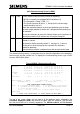
The unit will automatically attempt to determine whether MOVA should use its Bus /
MOVA (Digital) I/O Board or the enhanced serial link after complete initialisation, i.e.
INI=3 or first time power-up, as follows:
If one or more Bus / MOVA (Digital) I/O boards are fitted, then MOVA will initially
attempt to use the first Bus / MOVA (Digital) I/O board fitted (“MIO:1”).
If only LMU I/O boards are fitted and no Bus / MOVA (Digital) I/O boards, then MOVA
will initially not attempt to read any inputs or set any outputs (“MIO:0”). If the OMCU is
subsequently configured by the Instation to use the enhanced serial link, then MOVA
will also automatically attempt to use the enhanced 141 link (“MIO:2”).
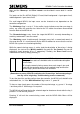
Regardless of what the unit decides, MOVA can be manually configured to use the first
Bus / MOVA (Digital) I/O board by entering “MIO=1” or to use the enhanced serial link
by entering “MIO=2”.
If MOVA is required to use a Bus / MOVA (Digital) I/O board,
always use the handset command SOP to check that the correct
I/O boards have been detected by the firmware (see page 249). However, if MOVA
is required to use the enhanced serial link, then check for ‘EEL:3’ (section 13.8)
and check that the controller firmware supports, and is configured to use serial
MOVA (section 4.2.6). The fault ‘MSF – MOVA Serial Fault’ will be raised if MOVA
cannot communicate over the link (see section 13.6.2 on page 226 for more
details on the OMCU/RMS fault log).
Important