
Specifications


GEMINI
2
Traffic Outstation Handbook
667/HB/32600/000 Page 189 Issue 11
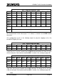
OTU – Reply Bit Allocation Table
Bit 7
Bit 6
Bit 5
Bit 4
Bit 3
Bit 2
Bit 1
Bit 0
Byte 0
GH
GG
GF
GE
GD
GC
GB
GA
Byte 1
Count
15
Count 0
HIOCC
7
HIOCC
0
Fault
DFM
Handset
Byte 2
Scoot 1
Scoot 1
Scoot 1
Scoot 1
Scoot 0
Scoot 0
Scoot 0
Scoot 0
Byte 3
Scoot 3
Scoot 3
Scoot 3
Scoot 3
Scoot 2
Scoot 2
Scoot 2
Scoot 2
Byte 4
Scoot 5
Scoot 5
Scoot 5
Scoot 5
Scoot 4
Scoot 4
Scoot 4
Scoot 4
Byte 5
Scoot 23
Scoot 23
Scoot 23
Scoot 23
Scoot 22
Scoot 22
Scoot 22
Scoot 22
Byte 6
Que 13
Que 2
Occ 14
Occ 1
Byte 7
< ---------------------- ENVIRONMENTAL SENSOR, BYTE 0 --------------------
>
Byte 8
< ---------------------- ENVIRONMENTAL SENSOR, BYTE 1 --------------------
>
NB: Environmental sensor data (bytes 7 & 8 above) is entered via the GED handset
command.
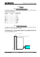
This configuration results in the following logical to physical mapping to the first
Bus/MOVA (Digital) I/O card:
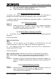
OTU – Digital Output Port Map
Bit 7
Bit 6
Bit 5
Bit 4
Bit 3
Bit 2
Bit 1
Bit 0
Port 0
FH
FG
FF
FE
FD
FC
FB
FA
Port 1
TC
DX
Output Ports 0 & 1 can be viewed using the SOP 0 command which will show all 16 bits
of these two ports. See handset command SOP, in section 13.8, starting on page 245.
OTU – Digital Input Port Map
Bit 7
Bit 6
Bit 5
Bit 4
Bit 3
Bit 2
Bit 1
Bit 0
Port 0
GH
GG
GF
GE
GD
GC
GB
GA
Port 1
Que 13
Count
0u
Count
0a
HIOCC
7
HIOCC
0
Fault
Port 2
Scoot 23
Scoot 22
Scoot 5
Scoot 4
Scoot 3
Scoot 2
Scoot 1
Scoot 0
Port 3
Cnt 15u
Cnt 15d
Cnt 15c
Cnt 15b
Cnt 15a
/Que 2
Occ 14
Occ 1
Input Ports 0 to 3 can be viewed using the DIP command. The display for this will show
8 bits for each port. See handset command DIP, in section 13.4, starting on page 220.
Note: