
Specifications


GEMINI
2
Traffic Outstation Handbook
667/HB/32600/000 Page 63 Issue 11
5. INSTALLATION
WARNING
THIS EQUIPMENT MAY ONLY BE INSTALLED IN A RESTRICTED ACCESS
LOCATION BY SIEMENS TRAFFIC CONTROLS OR BY TRAINED PERSONNEL.
AUTHORISED INSTALLER MUST ENSURE THAT INSTALLATION OF THIS
EQUIPMENT DOES NOT INTERFERE OR DEGRADE THE DESIGN SPECIFICATION
OF THE HOST EQUIPMENT IN ANY WAY WHATSOEVER.
ENSURE THAT THE UNIT IS NOT CONNECTED TO THE PSTN LINE DURING
INSTALLATION AND SWITCH OFF ALL MAINS TO CABINET PRIOR TO
STARTING.
THIS UNIT CONTAINS BATTERIES WHICH, UNDER FAULT CONDITIONS, MAY
LEAK HAZARDOUS SUBSTANCES.
CARE MUST BE TAKEN WHEN FITTING BATTERIES OR HANDLING THE UNIT.
FIT BATTERIES ONLY WITH SPECIFIED OR EQUIVALENT TYPE. BATTERIES
FITTED INCORRECTLY COULD CAUSE AN EXPLOSION.
THE UNIT IS ONLY COMPLETELY DISCONNECTED AND ISOLATED FROM THE
INCOMING MAINS SUPPLY WHEN THE MASTER SWITCH IN THE CONTROLLER
IS TURNED TO THE OFF POSITION. REMOVING THE MAINS LEAD IS NOT
SUFFICIENT.
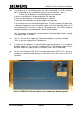
During a unit change out, the Green Voltage Detector connections can be left
intact on cableform 667/1/26586/000 that connects to the controller (as defined in
section 5.6.3 which starts on page 91).
For Graphos see the Graphos Product Handbook 667/HB/31200/000 (Section 2.3 –
Site Selection and Installation Guidelines) for the Installation Sequence.
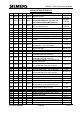
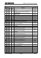
5.1 INSTALLATION CHECK LIST
The checklist on the following pages should be used to install the unit together with the
Instation computer printout for the equipment to be monitored. For further guidance on
each step refer to the appropriate section in the REFERENCE column. ‘WORKS
ORDER’ indicates that the relevant Works Order or Works Specification should be
consulted.
Installation techniques are shown on drawing 667/GA/26577/000 in Appendix B.
For GSM OMCU installation, see also 667/GA/32600/002 in Appendix B.
The checklist should be followed in sequence unless a particular step is not required.
Refer to the relevant column (OMCU, C/P [Car Park Count O/S], BUS [Processor],
MOVA, VC [Vehicle Classifier], UTMC OTU and UTMC VMS) to determine whether the
step applies to the application or applications that are required. For example, if the unit
is to perform both OMCU and Bus Processor facilities, then all activities in both the
‘OMCU’ and ‘BUS’ columns should be undertaken.