
Specifications


GEMINI
2
Traffic Outstation Handbook
667/HB/32600/000 Page 68 Issue 11
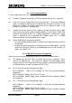
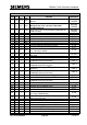
INSTALLATION CHECKLIST
STEP
OMCU
C/P
BUS
MOVA
FUNCTION
REFERENCE
1
OMCU
C/P
BUS
MOVA
Check unit supplied is as per installation
computer print out
WORKS
ORDER
2
OMCU
C/P
BUS
MOVA
Check unit contains correct I/O boards.
Ensure LMU I/O boards are issue 3 or
later if fitted with Bus/MOVA boards.
WORKS
ORDER
3
OMCU
C/P
BUS
MOVA
Check unit has the correct firmware loaded
into the FLASH memory.
WORKS
ORDER
4
OMCU
C/P
BUS
MOVA
Set up board address switches
5.2.1
5
OMCU
C/P
BUS
MOVA
Set up modem power selection
5.2.2
6
OMCU
C/P
—
—
Set up 50/60Hz operation selection
5.2.3
7
OMCU
—
—
—
Set up 120/230V AC operation selection
5.2.4
8
—
—
BUS
—
Set up RS485 terminating resistors
5.2.5
9
—
—
BUS
MOVA
Set up Bus/MOVA (Digital) output relay
resistors
5.2.6
10
OMCU
—
—
—
50V-0-50V voltage monitor required?
5.2.7
11
OMCU
C/P
BUS
MOVA
Switch the RAM battery on and confirm the
watchdog link is correctly installed
5.2.8
12
OMCU
C/P
BUS
MOVA
Install unit and connect safety earth lead to
cabinet earth point
5.3 to 5.5
13
OMCU
—
—
—
Connect serial linked Gemini
5.6.1
14
OMCU
—
—
—
Connect lamp current sensors (Unless using
ST800/700 enhanced serial link)
5.6.2.1
15
OMCU
—
—
—
Connect lamp supply sensor (Unless using
ST800/700 enhanced serial link)
5.6.2.2
16
OMCU
C/P
—
—
Connect mains voltage / 3
RD
Party ELV AC
detector cableforms
5.6.2.3
17
OMCU
C/P
—
—
Connect digital monitors cables (Unless
using ST800/700 enhanced serial link)
5.6.2.4
18
—
—
BUS
—
Connect CPU & Bus Processor digital I/O
5.6.3
19
—
—
BUS
—
Connect RS485 cables, e.g. for SIETAG
5.6.4
20
—
—
—
MOVA
Connect MOVA digital I/O cables (Unless
using ST800/700 enhanced serial link)
9.2 & 9.3
21
—
—
—
MOVA
Step deleted
22
OMCU
C/P
BUS
MOVA
Complete post installation check
5.6.6
23
OMCU
C/P
BUS
MOVA
Identify all connectors/cable forms
5.6.7
24
OMCU
C/P
BUS
MOVA
Connect all connectors to the unit
–
25
OMCU
—
—
MOVA
Connect 141 cable to controller handset port
(req’d for MOVA if using ST800/700 link)
5.6.8
26
—
—
BUS
—
Connect 141 cable to OTU handset port
(req’d for BUS if using OTU link)
5.6.9
27
OMCU
C/P
BUS
MOVA
Connect the unit to mains outlet
5.6.10
28
OMCU
C/P
BUS
MOVA
Restore controller and unit mains supply
–
29
OMCU
C/P
BUS
MOVA
Switch on unit supply
–
30
OMCU
C/P
—
—
Connect unit support battery
5.6.11
31
OMCU
BUS
—
Commission the OMCU / BUS applications
6
32
—
C/P
—
—
Commission the Car Park Count unit
6
33
—
—
—
MOVA
COMMISSION THE MOVA APPLICATION
9.5