
Specifications


GEMINI
2
Traffic Outstation Handbook
667/HB/32600/000 Page 69 Issue 11
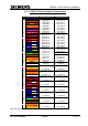
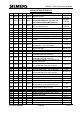
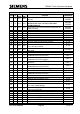
INSTALLATION CHECKLIST (contd.)
STEP
VC
UTMC
OTU
UTMC
VMS
FUNCTION
REFERENCE
1
VC
OTU
VMS
Check unit supplied is as per installation computer
print out
WORKS
ORDER
2
VC
OTU
VMS
Check unit contains correct I/O boards. Ensure LMU
I/O boards are issue 3 or later if fitted with
Bus/MOVA boards.
WORKS
ORDER
3
VC
OTU
VMS
Check unit has the correct firmware loaded into the
FLASH memory.
WORKS
ORDER
4
VC
OTU
VMS
Set up board address switches
5.2.1
5
VC
OTU
VMS
Set up modem power selection
5.2.2
6
—
—
—
Set up 50/60Hz operation selection
5.2.3
7
—
—
—
Set up 120/230V AC operation selection
5.2.4
8
VC
—
VMS
Set up RS485 terminating resistors
5.2.5
9
—
—
—
Set up Bus/MOVA output relay resistors
5.2.6
10
—
—
—
50V-0-50V voltage monitor required?
5.2.7
11
VC
OTU
VMS
Switch the RAM battery on and confirm the watchdog
link is correctly installed
5.2.8
12
VC
OTU
VMS
Install unit and connect safety earth lead to cabinet
earth point
5.3 to 5.5
13
—
—
—
Connect serial linked Gemini
5.6.1
14
—
—
—
Connect lamp current sensors (Unless using
ST800/700 enhanced serial link)
5.6.2.1
15
—
—
—
Connect lamp supply sensor (Unless using
ST800/700 enhanced serial link)
5.6.2.2
16
—
—
—
Connect mains voltage / 3
RD
Party ELV AC detector
cableforms
5.6.2.3
17
VC
—
—
Connect digital monitors cables (Unless using
ST800/700 enhanced serial link)
5.6.2.4
18
VC
OTU
VMS
Connect CPU & Bus Processor digital I/O
5.6.3
19
VC
—
VMS
Connect RS485 cables, e.g. for SIETAG
5.6.4
20
—
—
—
Connect MOVA digital I/O cables (Unless using
ST800/700 enhanced serial link)
9.2 & 9.3
21
—
OTU
—
Connect SCOOT, count and occupancy detectors
5.1.2(g)
22
VC
OTU
VMS
Complete post installation check
5.6.6
23
VC
OTU
VMS
Identify all connectors/cable forms
5.6.7
24
VC
OTU
VMS
Connect all connectors to the unit
–
25
—
—
—
Connect 141 cable to controller handset port (req’d
for if using ST800/700 link)
5.6.8
26
—
—
—
Connect 141 cable to OTU handset port (req’d for
BUS if using OTU link)
5.6.9
27
VC
OTU
VMS
Connect the unit to mains outlet
5.6.10
28
VC
OTU
VMS
Restore controller and unit mains supply
–
29
VC
OTU
VMS
Switch on unit supply
–
30
VC
OTU
VMS
Connect unit support battery
5.6.11
31
—
—
—
Commission the OMCU / BUS applications
6
32
—
—
—
Commission the Car Park Count unit
6