
Specifications

GEMINI
2
Traffic Outstation Handbook
667/HB/32600/000 Page 71 Issue 11
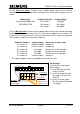
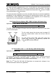
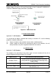
On each I/O board, only one of the three board address switches
should be in the ‘ON’ position while the unit is powered.
S5
S6
OR
OR
OR
PSU
CPU
Card
I/O Board #1
I/O Board #2
I/O Board #3
LMU I/O Board
Bus MOVA (Digital) I/O Board
Edge
of the
board
S1
1
4
ON
3
2
Edge
of the
board
1
5
6
ON
2
1
ON
2
ON
1
4
3
2
ON
1
4
3
2
ON
1
4
3
2
S1
ON
1
2
ON
1
2
ON
1
2
ON
1
2
ON
1
2
ON
1
2
LMU I/O
Board
Bus / MOVA
(Digital) I/O
Board
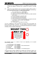
Figure 17 – I/O Board
Switch position 4 of S1 on the LMU I/O board is used for switching the lamp monitor
between 50Hz and 60Hz operation (OFF = 50Hz, ON = 60Hz), see section 5.2.3.
5.2.2 Modem Power Supply Selection (All Board Types)
Applicable To: OMCU, C/P, Bus, MOVA, Vehicle Classification, UTMC OTU & UTMC
VMS
5
Set up modem power selection
5.2.2
The Processor card normally provides the modem power. Two voltage supplies are
available on this card 5V (400mA) and 12V (1000 mA). If required an 8V (300mA)
supply is available on the LMU I/O, Bus/MOVA I/O and Digital I/O cards.
Check which supply is required by the modem using the Modem Supply List shown on
667/GA/32600/000 Sheet 2 in Appendix B.
Caution