
Specifications

GEMINI
2
Traffic Outstation Handbook
667/HB/32600/000 Page 72 Issue 11
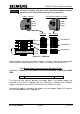
On the Processor board, insertion of the modem power lead into the relevant
connector socket in the Modem Power connector PL3 selects which supply to use as
follows.
Modem Type
Cableform Position
Voltage Supply
Dynalink PKS-5600-A-P/M
PL3 socket 3
5V Supply
GPRS/GSM TC35
PL3 socket 2
12V Supply
PL3 socket 1
0V Supply
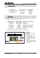
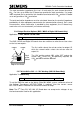
On the LMU I/O board, insertion of the modem power lead into the relevant connector
socket in the LMU analogue connector PL1 selects which supply to use as follows. The
orange link wire connects to the first relay on the board, which is used to control power
to the modem as part of its initialisation sequence.
Cableform Position
Voltage Supply
Wire colour of power cable
PL1 socket 27
Supply to Modem
Yellow wire
PL1 socket 28
Link (see below)
Orange wire
PL1 socket 29*
12V Supply
Orange wire (if 12V required)
PL1 socket 30
8V Supply
Orange wire (if 8V required)
PL1 socket 33*
5V Supply
Orange wire (if 5V required)
PL1 socket 34
Common Return
Black wire
* - This supply voltage is normally provided by the Processor card.
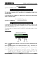
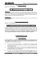
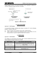
For Example:
To select 5V as the modem
power supply:
1) Insert the black wire into
socket 34 for 0V.
2) Insert the orange link wire
into sockets 28 and 33 to
select 5V.
3) Finally insert the yellow
wire into socket 27 (Modem
+ve supply).
PL1 Connector Viewed from the BACK
33
34
1
Yellow Wire:
Supply To The
Modem
Link To Required
Voltage For The
Modem, e.g. 5v
Black Wire:
Common Return
from the Modem
Orange Wire:
-
-
34
30
28
27
29
33
0v
31
32
5v
Relay
12v
8v
2