
Specifications

GEMINI
2
Traffic Outstation Handbook
667/HB/32600/000 Page 73 Issue 11
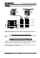
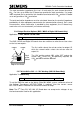
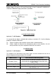
On the BUS / MOVA (Digital) I/O board, the modem power is
available on a separate connector PL4 which is located near the
front right-hand corner of the board. The orange wire is not
required as the necessary power switching for use during
initialisation is built into this board. If the modem power leads are
fitted with berg crimps, then the crimps should be cut
approximately in half to form a bullet which can be inserted into this
connector.
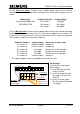
As with the LMU I/O card, the 12V and 5V connections are not normally used.
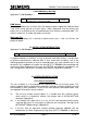
IMPORTANT
Before connecting the plug into the modem with the unit powered up, check with
a multi-meter that the correct power supply selection has been made.
0
8
12
5
PL4