
Specifications

GEMINI
2
Traffic Outstation Handbook
667/HB/32600/000 Page 75 Issue 11
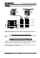
Connector
Position
Wire Colour
Description
1
Brown
Mains supply live
2
Blue
Mains supply Neutral
3
Green / Yellow
Mains supply Earth
4
Link to 5 for 110V working
5
Link to 4 for 110V working
6
Red
High voltage I/P No. 2 for Lamp Supply
Monitoring (see Notes. Not to be connected
when using the 3
RD
Party ELV AC LMU I/O
Board)
7
Yellow
High voltage I/P No. 1 for Controller Main
monitoring (not normally used for ST800/700)
(see Notes)
8
Black
High voltage I/P Return (Neutral)
9
External Power (GND)
10
External Power (13.8V)
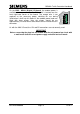
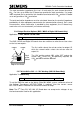
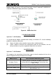
Before applying the mains’ power, recheck the correct voltage setting has been
selected for the Zero Crossover Mains’ Input (ZXO Mains I/P).
If 120V operation is required then a different variant of the Voltage Monitor Transformer
must be used. The 100V Welsh Office version is 667/7/25172/500, see section 5.2.7. A
design for a 120V version would need to be requested.
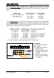
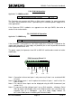
5.2.5 RS485 Terminating Resistors (BUS / MOVA I/O Board Only)
Applicable To: OMCU, VC & UTMC VMS
8
Set up RS485 terminating resistors
5.2.5
RS485 communication channels must be correctly terminated to allow reliable
operation. The termination load of each channel on the Bus / MOVA I/O board can be
set up using a number of switches as defined below.
Channel
Switch
Settings
Term’
Load
Switch
Settings
Term’
Load
Switch
Settings
Termination
Load
1
S2/1 on
S2/2 on
60
S2/1 on
S2/2 off
120
S2/1 off
S2/2 off
Not
Terminated
2
S4/1 on
S4/2 on
60
S4/1 on
S4/1 off
120
S4/1 off
S4/2 off
Not
Terminated
3
S3/1 on
S3/2 on
60
S3/1 on
S3/2 off
120
S3/1 off
S3/2 off
Not
Terminated
4
S1/1 on
S1/2 on
60
S1/1 on
S1/2 off
120
S1/1 off
S1/2 off
Not
Terminated