
Specifications

GEMINI
2
Traffic Outstation Handbook
667/HB/32600/000 Page 76 Issue 11
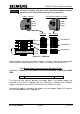
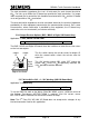
The total termination impedance (the ‘sum’ of both ends) for each channel should be
60 . For links up to 250m the I/O board can provide the total termination. If a longer
link is required, the far end of the link should be terminated with 120 and the I/O board
set to only provide a 120 termination.
The total termination impedance must be calculated, based on the terminal impedance
provided by all other equipment connected to the communication channel. So in some
circumstances, where termination is provided by that equipment, the I/O board may
need to be set to ‘not terminated’ (no resistors selected).
5.2.6 Output Resistor Options (BUS / MOVA & Digital I/O Boards Only)
Applicable To: Bus, MOVA & UTMC VMS
9
Set up Bus/MOVA (Digital) output relay resistors
5.2.6
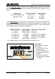
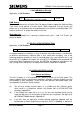
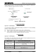
The BUS / MOVA and Digital I/O boards have two switches to select the resistor values
on the last two outputs:
The first switch selects the resistor values for output 15,
while the second switch selects the resistor value for
output 16.
The ‘ON’ position selects 22 , while ‘OFF’ selects the
normal 180 . Unless 22 is specifically required, the
180 position should be selected.
5.2.7 Welsh Office 50V – 0 – 50V Working (LMU I/O Board Only)
Applicable To: OMCU Only
10
50V-0-50V voltage monitor required?
5.2.7
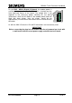
To set the OMCU to work on the Welsh Office 50V-0-50V system, a different variant of
the Voltage Transformer 667/7/25172/500 is required. Also the current sensor
667/7/25171/000 is limited to half the normal number of lamps.
Note: The 3
RD
Party ELV AC LMU I/O Board does not accept mains voltages of any
kind and cannot be used for this application.
1
Edge of the Board
Output
15
Output
16
Back
of the
Board
22
180
S7
ON
2