
Specifications

GEMINI
2
Traffic Outstation Handbook
667/HB/32600/000 Page 78 Issue 11
section 5.3, or use an Additional Outercase. If the Additional Outercase method
is used, then additional installation work is required (see section 5.7 on page
100).
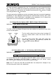
(d) If the unit is to be mounted in such a way that the ‘Battery Warning Label’ is
visible on the bottom of the unit then the following modifications are necessary.
This is to ensure that the battery is not operating upside down.
Ensure the Battery Fuse is not installed;
Temporarily dismantle the power supply unit;
Remove the metal cover (NB Do not remove any modem attached
to this cover);
Disconnect the battery connection leads;
Cut away the Battery retention tywraps;
Rotate the battery through 180 degrees;
Re-secure the battery using new tywraps, ensuring that the other
set of 4 holes is used. (See 667/GA/32600/000)
Replace the cover;
The Outstation is now ready for installation.
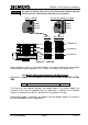
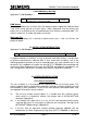
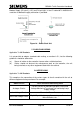
The unit is shipped with a label affixed to the front panel which clearly identifies the
battery terminal orientation, see below. This label should be removed when the unit
has been installed. If the arrows on the unit would point downwards after installation,
the battery must be rotated as detailed above.
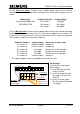
The Outstation comes in a number of basic units depending on the required
communication system:
with PSTN Modem 667/1/32600/001
with GSM Modem 667/1/32600/002 – Pole mounted antenna
with Car Park 667/1/32600/003
with UTMC 667/1/32600/004
with GSM Modem 667/1/32600/005 – Case mounted antenna
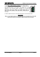
These part numbers provide a GEMINI
2
PSU (complete with LGD battery) together with
a GEMINI
2
Processor card and 0141 cable. The Basic Unit may require further