
Specifications

GEMINI
2
Traffic Outstation Handbook
667/HB/32600/000 Page 79 Issue 11
Expansion kits (either LMU I/O cards and/or Bus/MOVA (Digital) I/O cards) to support
the required application. Before the Outstation can be installed, these expansion kits
require assembling to the Basic Unit. To assemble these expansion kits to the Basic
unit, use the methods and Items Lists on General Assembly drawing 667/GA/32600/000
in Appendix B.
The following are important points to remember during assembly and installation when
the Outstation is fitted with LMU I/O boards:
Ensure that the rear cables (High Voltage and Low Voltage), are connected to
their monitoring points and plugged into the unit, before installing the unit into the
Rack or Cabinet.
If applicable – ensure that the Mains’ feed from the PSU assembly to the High
Voltage cable form is connected for the correct voltage; see section 5.2.4, which
starts on page 74.
Ensure that the voltage protection covers on the I/O board or boards are fitted and
securely fixed.
5.4.2 Radio Clock Installation
[This section only applies to Bus applications]
The optional Radio Clock is a separate unit that is mounted external to the Outstation
using a bracket supplied with the unit. It provides a time signal to the traffic outstation
received from the MSF Rugby transmitter. This is used to synchronise the internal real
time clock.
The system has good tolerance to interference and only requires valid reception for a
few minutes each day to maintain the accuracy of the clock. It is however a sensitive
radio receiver operating at 60 KHz (for Rugby MSF transmissions) and certain
precautions are necessary.
It should not be located near to radio transmitters.
It should be kept as far away as practicable from a SIETAG reader or vehicle
detector loops. In some cases detector loops might have to be set to operate
on different channels as they can radiate at the same frequency as the
Rugby transmitter.
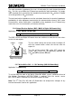
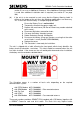
It must be orientated correctly to point towards the Rugby transmitter. See
below and also see ‘RCS’ on page 252 for details on the use of the handset
for verifying radio reception.
Cabling to the Radio Clock should be separate from other intersection cables,
particularly detector loop feeders, to avoid electrical noise being injected into the Radio
Clock via its supply. A screened cable is recommended.
The Radio Clock is required to be connected to a digital input on either the Processor or
the Bus / MOVA (Digital) I/O Boards (defined during the configuration process) and to
signal ground. The current version of the radio clock derives power from its internal
battery and no additional power connection is required. Earlier versions (with 3-core
connection cable) require an external supply, which may be derived from the Processor