
Specifications


GEMINI
2
Traffic Outstation Handbook
667/HB/32600/000 Page 81 Issue 11
This is not an exhaustive list and other applications exist. The following sub-sections
detail the methods for the interfaces mentioned...
The connection methods to be used when monitoring Controller Lamp Voltages are as
described in sections 5.6.1 and 5.6.2 below:
5.6.1 Serial Linked
13
Connect serial linked Gemini
5.6.1
The basic Lamp Monitoring configuration requires a TR0141 cable connection back to
the Controller (see Figure 2 on page 19). The cableform (667/1/26579/000) is installed
between PL4 on the Outstation and the handset connector on the Controller CPU.
Note that the cableform 667/1/26586/800 (High Voltage Serial Link) is not required as
the high voltage monitoring is wired as defined below.
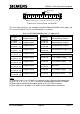
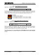
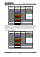
Connect the wires from PL1 on the Outstation PSU as follows:
Pin No.
Wire
Colour
MDU on ST800
controller
Phase Driver PCB on
ST700 controller
PL1.6
RED
Lamp Supply
PL2.10
SK2 Pin 6
PL1.8
BLACK
Neutral
PL2.224 (or Neutral
connection on back
panel)
SK1 Pin 3
Leave coiled
YELLOW
Not required
Not required
Note: for Lamp Supply connection on an ELV controller, see Note 4 of section 5.2.4.
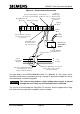
5.6.2 Freestanding
For Lamp Monitoring purposes, the cable required for a freestanding Outstation (used
with any controller other than ST800/700) is the High Voltage Detector cableform
667/1/26586/000. Refer to Figure 3 on page 19 for details.
Note: For Lamp Monitoring purposes, the Outstation in freestanding mode is equivalent
to the older freestanding OMU.
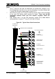
For the connections required, see sections 5.6.2.1 to 5.6.2.4 and Figure 19. Do not
connect the Red, Yellow or Black leads from PL1 on the PSU.
5.6.2.1 Current Sensors and Digital Outputs Connections
Applicable To: OMCU Only
14
Connect lamp current sensors
5.6.2.1
The current sensors must not be fitted to mains’ leads carrying current
unless they are plugged into their respective LMU I/O boards to
terminate them; otherwise they may produce a high voltage.
Warning