
Specifications


GEMINI
2
Traffic Outstation Handbook
667/HB/32600/000 Page 82 Issue 11
Each controller signal output, which is to be monitored, requires one current sensor as
described on the RMS Instation computer printout. Examples of output types to be
monitored are indicated in the following list. They all require one current sensor unless
otherwise stated:
(a) Each 3-aspect vehicle phase
(b) Each 2-aspect pedestrian phase
(c) A 3-aspect pelican vehicle phase
(d) A 2-aspect pelican pedestrian
(e) Each group of wait lamps associated with the same pedestrian phase
(f) Each green arrow (or filter) phase
(g) Each switched sign phase
(h) If regulatory signs are to be monitored then they need to be grouped together
(i) Each “flashing amber signal group” phase requires one or two current sensors,
depending on monitoring requirements (this phase type is applicable to export
signal sequences only)
Each current sensor can monitor currents up to 4.25A RMS.
If the nominal load current (not including the red/ambers) of a particular controller
output exceeds approximately 4.0A RMS, then that output should be split and treated
as two separate outputs.
The maximum regulatory sign load is restricted to 7 signs (21 tubes) per input
(choke/ballast types only allowed).
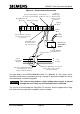
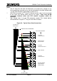
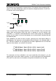
The current sensors measure the current flowing in the wires that are passing through
their core. To maintain the correct relationship between the current flowing in the
conductor and the output from the sensor, the sensors must be connected the correct
way round (see following diagram).