
Specifications


GEMINI
2
Traffic Outstation Handbook
667/HB/32600/000 Page 83 Issue 11
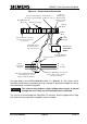
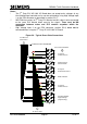
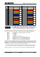
Figure 19 – Current Sensor Connection
Berg Mini-Latch
Housing
Polarisation Pip
Voltage
Monitoring
Transformer
Input on I/O
Board 1
First Current Input on I/O Board 1
(Second Current Input on Boards 2 & 3)
To
Lamp
Supply
From
Controller
Output
R
A
To
Lamps
G
(In this example the Output
being monitored is a
3 Aspect Vehicle Phase)
Red Spot Marking on Current
Sensor must point in the
direction shown
34
33
1
2
End Connector Socket
Positions Not Used at
both ends
White
Wire
Orange
Wire
Red Wire must
be Connected to
top of Connector
Current Sensor
Voltage Monitor
Transformer
Not used on
serial linked
OMCU
For more details see 667/GA/32600/000 sheet 2 in Appendix B. The current sensor
should be mechanically secured by passing a tywrap or equivalent through the sensor
hole and around a suitable fixing point.
The sensors may produce a high voltage when current is passed
through the core if they are not terminated into an I/O Board.
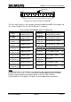
The sensors are terminated with Berg Mini PV terminals and are clipped into a Berg
mini latch housing, to provide a complete sensor assembly...
Caution