
Specifications


GEMINI
2
Traffic Outstation Handbook
667/HB/32600/000 Page 84 Issue 11
34
33
1
2
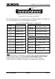
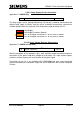
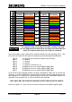
End Connector Socket Positions Not Used
Polaring
Pip
Connector Viewed from the BACK
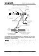
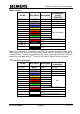
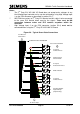
The mini latch housing is the Analogue connector 508/4/26138/002, which plugs into
PL1 on the I/O Board. The PL1 circuit allocation is as follows:
Also see 667/GA/32600/000 sheet 2 in Appendix B
Pin No.
Description
Pin No.
Description
PL1 pin 1
Analogue Input 1 [1]
PL1 pin 21
Isolated Relay Output 1
PL1 pin 2 [2]
PL1 pin 22
PL1 pin 3
Analogue Input 2
PL1 pin 23
Isolated Relay Output 2
PL1 pin 4 [2]
PL1 pin 24
PL1 pin 5
Analogue Input 3
PL1 pin 25
Isolated Relay Output 3
PL1 pin 6 [2]
PL1 pin 26
PL1 pin 7
Analogue Input 4
PL1 pin 27
Isolated Relay Output 4 [3]
PL1 pin 8 [2]
PL1 pin 28
PL1 pin 9
Analogue Input 5
PL1 pin 10 [2]
Pin No.
Description
PL1 pin 11
Analogue Input 6
PL1 pin 29
+12V modem supply [4]
PL1 pin 12 [2]
PL1 pin 13
Analogue Input 7
PL1 pin 30
+8V modem supply [4]
PL1 pin 14 [2]
PL1 pin 15
Analogue Input 8
PL1 pin 31
Not used
PL1 pin 16 [2]
PL1 pin 32
PL1 pin 17
Analogue Input 9
PL1 pin 33
+5V modem supply [4]
PL1 pin 18 [2]
PL1 pin 19
Analogue Input 10
PL1 pin 34
0V common return [4]
PL1 pin 20 [2]
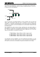
Notes:
[1] ‘Analogue Input 1’ on I/O Board 1 is reserved for the voltage monitor transformer.
[2] Pins 2, 4, 6, 8, 10, 12, 14, 16, 18 and 20 are commoned on the LMU I/O Board.
[3] Reserved for controlling the modem power on the first LMU I/O board.
[4] See section 5.2.2 on page 71 for details on the modem power connections.