
Specifications


GEMINI
2
Traffic Outstation Handbook
667/HB/32600/000 Page 85 Issue 11
5.6.2.2 Lamp Supply Sensor Connection
Applicable To: OMCU Only
15
Connect lamp supply sensor
5.6.2.2
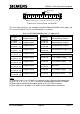
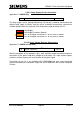
The lamp supply sensor (Voltage Monitoring Transformer) should be connected to the
cabinet lamp supply as follows and the sensor should be mechanically secured to a
suitable location within the controller. See the previous page for details on PL1.
Red
Lamp Supply
Black
Lamp Supply Common (Neutral)
Orange
Pin 1 of Analogue Connector PL1 of first LMU I/O Board
White
Pin 2 of Analogue Connector PL1 of first LMU I/O Board
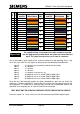
5.6.2.3 Green Voltage Detector Connections
Applicable To: OMCU and Car Park
16
Connect mains voltage / 3
RD
Party ELV AC
detector cableforms
5.6.2.3
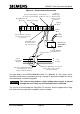
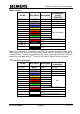
With the exception of the regulatory signs, each controller output monitored requires a
connection to the green lamp drive voltage for that output. For single aspect outputs,
the drives to those aspects are used in place of the green signal.
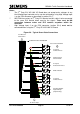
Connection to the unit is via cableform 667/1/26586/000 and each state connection
must be terminated, as indicated in Figure 20, and as detailed in the Instation Computer
Printout.