
Specifications


GEMINI
2
Traffic Outstation Handbook
667/HB/32600/000 Page 86 Issue 11
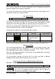
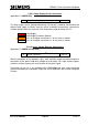
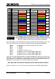
Mains Voltages:
Pin No.
Wire Colour
Description
All Controllers
(except
ST800/700)
PL2 PIN 1
WHITE
Input 1
Controller Mains
PL2 PIN 2
GREY
Input 2
Green Drive A
PL2 pin 3
VIOLET
Input 3
Green Drive B
PL2 pin 4
BLUE
Input 4
Etc…
PL2 pin 5
YELLOW
Input 5
See note below
PL2 pin 6
ORANGE
Input 6
PL2 pin 7
RED
Input 7
PL2 pin 8
BROWN
Input 8
PL2 pin 9
GREEN
Input 9
PL2 pin 10
PINK
Input 10
PL2 pin 11
RED
Leave open circuit ZXO derived from PSU
module.
PL2 pin 12
BLACK
Common NEUTRAL (for above inputs).
PL2 pin 13
Leave open circuit ZXO derived from PSU
module.
PL2 pin 14
BLACK
Leave open circuit ZXO derived from PSU
module.
Note: This connector is also used by the OMCU to monitor the state of other mains
level signals, such as the controller’s mains supply (after its switches and fuses) for
example, which is normally connected to the first mains state input on the first LMU I/O
board. Does not apply to the 3
RD
Party ELV AC LMU I/O Board. Please see below.
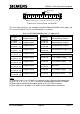
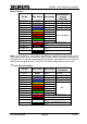
3
RD
Party ELV AC Voltages:
Pin No.
Wire Colour
Description
3
RD
Party ELV
Controllers
PL2 PIN 1
WHITE
Input 1
Unused *
PL2 PIN 2
GREY
Input 2
Green Drive A
PL2 pin 3
VIOLET
Input 3
Green Drive B
PL2 pin 4
BLUE
Input 4
Green Drive C
PL2 pin 5
YELLOW
Input 5
Etc…
PL2 pin 6
ORANGE
Input 6
PL2 pin 7
RED
Input 7
PL2 pin 8
BROWN
Input 8
PL2 pin 9
GREEN
Input 9
PL2 pin 10
PINK
Input 10
PL2 pin 11
RED
Leave open circuit ZXO derived from PSU
module.
PL2 pin 12
BLACK
Common NEUTRAL (for above inputs). **
PL2 pin 13
Leave open circuit ZXO derived from PSU
module.
PL2 pin 14
BLACK
Leave open circuit ZXO derived from PSU
module.