
Specifications


GEMINI
2
Traffic Outstation Handbook
667/HB/32600/000 Page 88 Issue 11
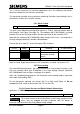
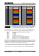
5.6.2.4 Digital Monitor Connections (LMU I/O Board Only)
Applicable To: OMCU, VC and Car Park
17
Connect digital monitors cables
5.6.2.4
Digital Monitor points within the controller should be connected using the cableform
667/1/26585/000 as detailed on the Instation Computer Printout.
The connectors for these cableforms are on the underside of the board; i.e. on the
opposite side to the mains’ states connector. The silk-screening for their identifications
(PL3 and PL4) and arrows are located on the topside of the board, near the edge.
These Inputs are not polarity conscious, but are voltage conscious. This means they
are connected one way for 24V logic working and the other way for 5V logic working.
Hence the method of selecting 24V or 5V working is by reversing the inputs to the I/O
Board.
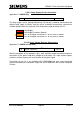
For installations with 24V working the odd numbered pin on each input should be
connected to the 24V controller supply, and the even numbered pin connected to the
controller input / detector output. For Installations with 5V working the opposite is true,
with the even numbered pin being connected to the controller 5V supply.
The ribbon cable should not be connected to 0V in either situation as this will invert the
input and may cause unstable operation.
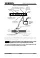
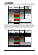
For example, referring to the first extra low voltage input, then for 24V working, connect
the brown lead from PL4 pin 1 to the +ve signal (24V Supply) and the red lead from PL4
pin 2 to the –ve signal (controller input / detector output).
For 5V working, connect the red lead from PL4 pin 2 to the +ve signal and the brown
lead from PL4 pin 1 to the –ve signal.
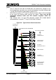
Controller +24V
supply
Controller
Input
OMCU Inputs
0V
Detector Relay
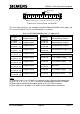
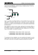
If the correct method is used for the inputs voltage level, but occasional false detections
or drop outs are being experienced, a diode (1N4007) can be installed between the
digital input on the LMU I/O board and the controller input. This prevents any noise on