
Specifications


GEMINI
2
Traffic Outstation Handbook
667/HB/32600/000 Page 89 Issue 11
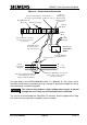
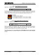
the controller input triggering the ‘reverse circuits’ (For example, when monitoring 24V
signals, if the signal voltage goes above the common voltage by between 1V to 3V the
5V monitor circuit will be triggered.)
Controller +24V
supply
Controller
Input
OMCU Inputs
0V
Optional Diode
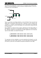
There are two Extra Low Voltage cableforms to each I/O Board. They are made from
ribbon cable and therefore need to be spilt as required to suit the routing at the
installation. It is therefore recommended that care be taken during the configuration
process at the Instation, to ensure that detectors on a terminal block should not be split
over different ports.
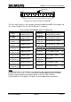
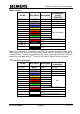
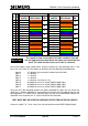
Each cableform can cater for up to 8 inputs, and have the same colour coding, as
defined below. The input ports are allocated to LMU I/O Boards in the following order. If
Bus / MOVA I/O boards are also fitted, then the OMCU application can also read the
inputs on those boards, see section 5.6.3 overleaf.
1
st
LMU I/O Board
Ports 0 (PL4) & 1 (PL3)
Inputs 1 to 16
2
nd
LMU I/O Board
Ports 2 (PL4) & 3 (PL3)
Inputs 17 to 32
3
rd
LMU I/O Board
Ports 4 (PL4) & 5 (PL3)
Inputs 33 to 48
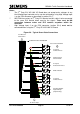
The connectors for these cableforms are on the underside of the board; i.e. on the
opposite side to the mains’ states connector. The silk-screening for their identifications
(PL3 and PL4) and arrows are located on the topside of the board, near the edge.