Documentation HiPath 1100 V7.0 HiPath 1120 Installation Guide Communication for the open minded Siemens Enterprise Communications www.siemens-enterprise.
Contents Contents 0 1 Important Information. . . . . . . . . . . . . . . . . . . . . . . . . . . . . . . . . . . . . . . . . . . . . . . . . . 1-3 1.1 Safety Information . . . . . . . . . . . . . . . . . . . . . . . . . . . . . . . . . . . . . . . . . . . . . . . . . . . . 1-3 1.1.1 Safety Information: danger . . . . . . . . . . . . . . . . . . . . . . . . . . . . . . . . . . . . . . . . . . 1-5 1.1.2 Safety Information: warning. . . . . . . . . . . . . . . . . . . . . . . . . . . . . . . . . . . . . . .
Contents 3.9.1 HiPath 1120 . . . . . . . . . . . . . . . . . . . . . . . . . . . . . . . . . . . . . . . . . . . . . . . . . . . . . 3.10 Installing a USB Interface . . . . . . . . . . . . . . . . . . . . . . . . . . . . . . . . . . . . . . . . . . . . . 3.10.1 On the HiPath 1120 . . . . . . . . . . . . . . . . . . . . . . . . . . . . . . . . . . . . . . . . . . . . . . 3.11 Installing an external Audio Source. . . . . . . . . . . . . . . . . . . . . . . . . . . . . . . . . . . . . . 3.
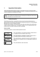
Important Information Safety Information 1 Important Information HiPath 1100 Telecommunications Systems are compatible with TN-S and TN-C-S power systems featuring a PEN conductor divided into two parts: a safety ground conductor (PE) and a neutral conductor (N) as defined in IEC 364-3. ! 1.1 Warning Only service and installation personnel should open the PABX box and/or connect and handle trunk and extension lines.
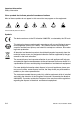
Important Information Safety Information Other symbols that indicate potential hazardous situations Most of these symbols do not appear in this manual but may appear on the equipment. Electricity Weight Heat Fire Chemicals ESD* Laser *Electrostatically Sensitive Device Symbols The device conforms to the EU directive 1999/5/EU, as attested by the CE mark. This device has been manufactured in accordance with our certified environmental management system (ISO 14001).
Important Information Safety Information 1.1.1 Safety Information: danger Ground Safety Ensure that all proper ground connections have been made before operating the system. Never operate the equipment before connecting the ground wire. Dangerous Voltages Voltages higher than 30 VAC (alternating current) or 42 VDC (direct current) are classified as dangerous voltages (EN 60950). Damage ● Replace the power cord immediately if there is any sign of damage.
Important Information Safety Information 1.1.2 Safety Information: warning Hazards when working with large gauge cables Low voltages and large gauge cables increase the risk of hazardous situations. While large gauge cables are usually of low voltage, their current values are higher. This results in higher risk, specifically in the event of a short-circuit. Protective Clothing/Equipment ● When working with the equipment, do not wear loose-fitting clothes. Contain long or freeflowing hair.
Important Information Safety Information 1.1.3 Safety Information: Caution Checking and Measuring Voltage ● Check rated voltage for recommended system installation. ● Proceed very carefully when making measurements on live components or when servicing equipment with the power on. Damage Only use tools and equipment that are in perfect condition. Do not operate equipment that is damaged. Report any problems to your supervisor.
Important Information Safety Information 1.1.4 General Information Line/Cable Connections ● All cables coming out of the system must be protected along their entire path inside conduits, ducts or other appropriate routes of conveyance. ● Cables must be connected only to their specified connections points. Location of Safety Equipment Once maintenance is finished, return all safety equipment to its proper location. Inspecting your Tools Inspect tools regularly.
Important Information Safety Information 1.1.5 What to do in Case of an Emergency Procedures to follow during Accidents ● In the event of an accident stay calm and proceed with caution. ● Turn off the power before touching the victim of an electrical accident. ● If the power cannot be shut down immediately, use an object made of a non-conductive material such as wood to touch the victim and isolate him/her from any electrical current.
Important Information Data Protection and Confidentiality 1.2 Data Protection and Confidentiality Handling of Personal Information This telephone exchange uses and processes personal information (call detail records, display messages, and customer data records, for instance). Comply with all local and country-specific laws and regulations concerning use and protection of such information.
Important Information Structure of this Manual 1.3 Structure of this Manual Introduction This manual provides information about the HiPath 1100 Communications Systems. This manual was designed to provide information in information mapping format. It is divided into sections and units that present, as clearly as possible, all steps required to perform specific tasks when operating the system. It makes it easy for technical personnel to find the information needed and learn it quickly.
System Data Overview 2 System Data 2.1 Overview This manual describes the HiPath 1120 systems and their characteristics. Read all the chapters in this manual carefully. Only trained technical personnel should handle and service this system. 2.2 HiPath 1120 System Periphery Profiset External analog lines Analog extensions Sensor and Relay Audio Device c/d a/b a/b S1/RL1 Internal entrance telephone Extension Basic Access (Public Network) ISDN S0 4x Mini DIN-6 MO V.
Installation HiPath 1100 Installation 3 Installation 3.1 HiPath 1100 Installation About this Chapter This chapter contains information on: ● Installing the interface HiPath 1100. More information on additional equipment and expansions can be found in the Service Manual ● Configuration (installation of modules). ! Danger Only authorized technical personnel should install this system. 3.
Installation Select the location for installing the equipment Step Installation procedures (Information) 7. “Connections to the System” 3-29 8. “Installing a USB Interface” 3-31 9. “Installing an external Audio Source” 3-32 10. “Installing a TFE - entrance telephone interface” 3-32 11. “Installing telephone terminals” 3-33 12. “Performing a visual inspection” 3-35 Table 3-1 ! 3.
Installation Unpacking system components 3.4 Unpacking system components Procedure Step Procedure 1. Check to see that all components listed on the receipt are included in the package. 2. Inspect all items for any damage that may have occurred during transportation. If any damage occurred, report it immediately to the place of purchase. 3. Discard packaging materials according to national environmental regulations. ! Warning Use only equipment and systems that are in perfect condition.
Installation Getting to know your systems Opening the Main Distribution Frame Figure 3-2 Opening the HiPath 1120 Main Distribution Frame Location of components Figure 3-3 3-16 System installation overview HiPath 1120 HiPath1120, Installation Guide
Installation HiPath 1120 wall mounting instructions 3.6 HiPath 1120 wall mounting instructions Step Procedure 1. Drill a hole in the wall at a height of 4.10 ft from the floor. 2. Place the bushing over the hole then insert the screw and tighten it until only 0.19" protrude. 3. Hang the system at the top of ➀, on the screw (see figure 3-4). 4. Mark additional holes for washers ➁ and remove the system. 5.
Installation Installing modules To help you configure the systems, we suggest that you use the Service Manual, the HiPath 1100 Manager, in off-line mode, to obtain a visual illustration of the module locations and external lines and the resulting numbering plan (see Help - Advanced Configuration/PABX Information for further information). 3.7.
Installation Installing modules 3.7.3 Installing modules 3.7.3.1 On the HiPath 1120 Installation Procedures Step * Procedure 1. Turn off the power supply. 2. Remove the system’s cover 3. Insert the module into one of the slots shown in figure 3-5. 4. Underside: To install the LAN Interface Module or Music Module, lift the top part (MB) of the system and use the pin bar to connect with X1 position of the LAN Interface Module or X2 position of the Music Module. 5.
Installation Installing modules 3.7.4 ADSL Connection in the LAN interface modules 3.7.4.1 ADSL module Connection procedure Step Procedure 1. Connect the carrier’s ADSL line to slot 1 and 2 of the X2 Connector. 2. Connect slots 3 and 4 of the X2 Connector to the external line input for the HiPath 1100. 3. Connect your network cables to the HUB (J3, J5, J6 and J7 Connectors). 3.7.4.2 SLIMC, SADSLIM modules Connection procedure Step Procedure 1.
Installation Installing modules 3.7.5 Installing a Baby Board ADSL module Installation Procedures Step Procedure 1. Select the SLIMC module. The Baby Board is a Modem for ADSL over POTS and will not support ADSL over ISDN (an external Modem must be used in case of ADSL over ISDN). 2. Attach the separators provided with the module. 3. Attach the Baby Board ADSL module to the separators. 4. Connect the cable of the Ethernet Interface to the X6 Connectors. 5.
Installation Installing modules 3.7.6 Installing an EVM module Installation Procedures Step Procedure 1. Turn off the power supply. 2. Remove the system’s cover 3. Attach the separator provided with the module to the MB. 4. Attach the module to the MB’s pin Connector and to the separator. 5. Reassemble the entire set. 6. “Performing a visual inspection” on page 3-35. 7. Turn on the power supply. 8. Configure the required data (see Service Manual).
Installation Installing modules 3.7.7 Installing a Baby Board VCC module (Voltage Conditioner Circuitry) Installation Procedures Step Procedure 1. Turn off the power supply. 2. Remove the system’s cover 3. Attach the separator provided with the module to the MB. 4. Attach the module to the MB’s pin Connector and to the separator. 5. Reassemble the entire set. 6. “Performing a visual inspection” on page 3-35. 7. Turn on the power supply. 8.
Installation Installing modules 3.7.8 Installing a ISDN / S0 module Installation Procedures Step Procedure 1. Turn off the power supply. 2. Remove the system’s cover 3. Attach the module to the corresponding Connector on the MB 4. Reassemble the entire set. 5. “Performing a visual inspection” on page 3-35. 6. Turn on the power supply. 7. Configure the required data (see Service Manual).
Installation Installing modules HiPath 1120 S0 module jumpers X2 - Port 1 Configuration X3 - Port 2 Jumper Pos. Configuration Jumper Pos.
Installation Installing modules 3.7.9 Installing a CTR- UP0/E module The line length of the analog stations is restricted to 100m when using comfort telephones. Installation Procedures Step Procedure 1. Turn off the power supply. 2. Remove the system’s cover 3. Attach the module to the corresponding Connector on the MB 4. Reassemble the entire set. 5. “Performing a visual inspection” on page 3-35. 6. Turn on the power supply. 7. Configure the required data (see Service Manual).
Installation Installing modules 3.7.10 Installing a Music module Installation Procedures Step Procedure 1. Turn off the power supply. 2. Remove the system’s cover 3. Raise the system’s top slot (MB). 4. Insert the module in the slot shown on figure 3-12. 5. Attach the MB to the module. 6. Make the connections to the appropriate module Connector. 7. Reassemble the entire set. 8. “Performing a visual inspection” on page 3-35. 9. Turn on the power supply. 10.
Installation Installing the power supply 3.8 Installing the power supply Introduction Before connecting the power supply to the system, see Service Manual. 3.8.1 On the HiPath 1120 Installation Procedures Step Procedure 1. Check network voltage 2. If the voltage is within the power supply’s voltage range, connect the power supply. 3. “Performing a visual inspection” on page 3-35 4. Configure the required data (see Service Manual).
Installation Connections to the System 3.9 Connections to the System Introduction Attach cables to the system’s Main Distribution Frame (MDF) and route them through the conduits and openings to reach the carrier’s main telephone distribution cabinet. Below are some examples of configurations. 3.9.1 HiPath 1120 Example *The installation of a Profiset 3030 system telephone requires a CD pair in conjunction with an A/B extension slot (see “Installing telephone terminals” on page 3-33).
Installation Connections to the System When using Expansion module UP0/E, Profiset 3030 system telephone or optiPoint could be assigned as attendant but the c/d lines will be reduced from 4 to 2 cd lines. The line length of the analog stations is restricted to 100m when using comfort telephones.
Installation Installing a USB Interface 3.10 Installing a USB Interface Introduction To connect a PC to the HiPath 1100 using a USB interface you must have a USB adapter cable. This interface allows you to use certain applications developed specifically for configuring and managing user features. 3.10.1 On the HiPath 1120 Figure 3-15 Illustration of USB cable connection Connections Step Procedure 1.
Installation Installing an external Audio Source 3.11 Installing an external Audio Source The HiPath 1100 systems provide connections for audio devices, such as radios, tuners, CD, MD, and others. ● HiPath 1120 The audio source must be connected to a music optional module using an RCA Connector in slot X1 (see Figure 3-14 on page 3-29). 3.12 Installing a TFE - entrance telephone interface 3.12.
Installation Installing telephone terminals 3.13 Installing telephone terminals A Profiset 3030 System Telephone has four wires (A, B, C, D), two used for voice (A, B), and two for data (C, D). An optiPoint-type system telephone has four wires (A, B, C, D), two of which (A, B) are required for voice communications. A Standard Telephone (DP/MF) has only two wires (A, B), both used for voice.
Installation optiPoint Master/Slave telephone HiPath 1120 connections 3.14 optiPoint Master/Slave telephone HiPath 1120 connections Figure 3-17 ! 3-34 optiPoint Master/Slave telephone HiPath 1120 connections Important When there are more than 4 optiPoint 500 (Master or Slave) telephones on the HiPath 1120 system, an additional power supply must be used. (see Service Manual).
Installation Performing a visual inspection 3.15 Performing a visual inspection Introduction Before starting up the system, perform a visual inspection of all hardware, cables and power supply. This procedure should be performed with the entire system turned OFF. . Warning ! Check whether all AC and DC connections of the cables, modules and chassis of the HiPath 1100 are correctly and properly connected before connecting the client interface.
Programming mode Language 4 Programming mode You can change the default settings of the HiPath 1100 to fit your needs. An MF-type or system telephone can be used for this purpose, or a PC with the HiPath 1100 Manager administration software installed. The instructions that follow refer to the factory default settings. For further information please refer to the HiPath 1100 Programming Manual. 4.1 Language Defines the language for displaying messages on the system telephone display.
Programming mode Country/group of countries 4.2 Country/group of countries To configure the settings correctly select the country where the system will be used. Required: Programming mode must be activated (*95 31994). eji w Enter the programming code. p w Enter the code for the country or group of countries as shown on the table below (e.g., "03" for Portugal). w The system restarts after the change is made. 4.2.0.1 Code Table for Countries and groups of Countries.
Programming mode Country/group of countries Code Group Countries Display Language 09 IM English Saudi Arabia Bahrain Egypt United Arab Emirates Ghana Yemen Iran Jordan Kuwait Libya Nigeria Oman Kenya Zimbabwe Syria Sudan Tanzania Serbia/ Montenegro English 10 IM French Algeria Cameroon Ivory Coast Lebanon Morocco Senegal Tunisia French 11 China China English 12 Malaysia Malaysia English 13 Singapore Singapore English 14 Thailand Thailand English 15 Greece Greece English 16
Programming mode Country/group of countries Code Group Countries Display Language 24 Canada Canada English 25 South Africa South Africa English 26 Turkey Turkey English 27 Latvia Latvia English 28 Lithuania Lithuania English 29 Italy Italy English 30 Australia Australia English 31 United Kingdom United Kingdom English 33 France France French 34 Korea Korea English 35 Germany Germany German 36 Netherland Netherland Dutch 37 Belgium Belgium Dutch French
Programming mode Country/group of countries 4-40 HiPath1120, Installation Guide
Abbreviations 5 Abbreviations General list This list presents the abbreviations used in this manual.
Abbreviations Table 5-1 Abbreviation IND ISDN LAN MB MDF MF MO MOH MSN NT PABX PC PEN PMP PP PSU RSA RTC RTS RUF RxD S0 SPA SW TAPI TFE TN-C-S TN-S TxD UCD USB VMIe 5-42 Abbreviations Meaning India Integrated Services Digital Networks Local Area Network Basic Module Main Distribution Frame Analog Multifrequency telephone Optional Module Music on Hold Multiple Subscriber Number Network Terminator Private Automatic Branch Exchange Personal Computer Protection Conductor plus Neuter conductor Point Multipoin
Index Z A Accident Report 1-9 C CE mark 1-4 Connecting extensions to the system’s Internal MDF 3-29 Country 4-37 D Data Protection and Confidentiality 1-10 Dimensions of the HiPath 1120 system 3-15 S Safety Information 1-3 caution 1-7 warning 1-6 Safety information danger 1-5 Safety Symbols 1-3 Select the location for installing the equipment 3-14 System Data 2-12 U Unpacking system components 3-15 W What to do in Case of an Emergency 1-9 G Getting to know your systems 3-15 H HiPath 1100 System Ins
44 HiPath 1120, Installation Guide
Copyright © Siemens Enterprise Communications GmbH & Co. KG 06/2008 Hofmannstr. 51, D-80200 München Siemens Enterprise Communications GmbH & Co. KG is a Trademark Licensee of Siemens AG Reference No.: A31003-K1270-J100-1-7631 Communication for the open minded Siemens Enterprise Communications www.siemens-enterprise.